Current interrupter system
A technology of current breaker and circuit breaker, which is applied in the field of current circuit breaker system and can solve problems such as economic balance burden
- Summary
- Abstract
- Description
- Claims
- Application Information
AI Technical Summary
Problems solved by technology
Method used
Image

Examples
Embodiment Construction
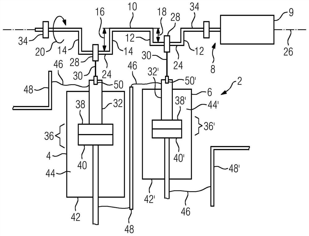
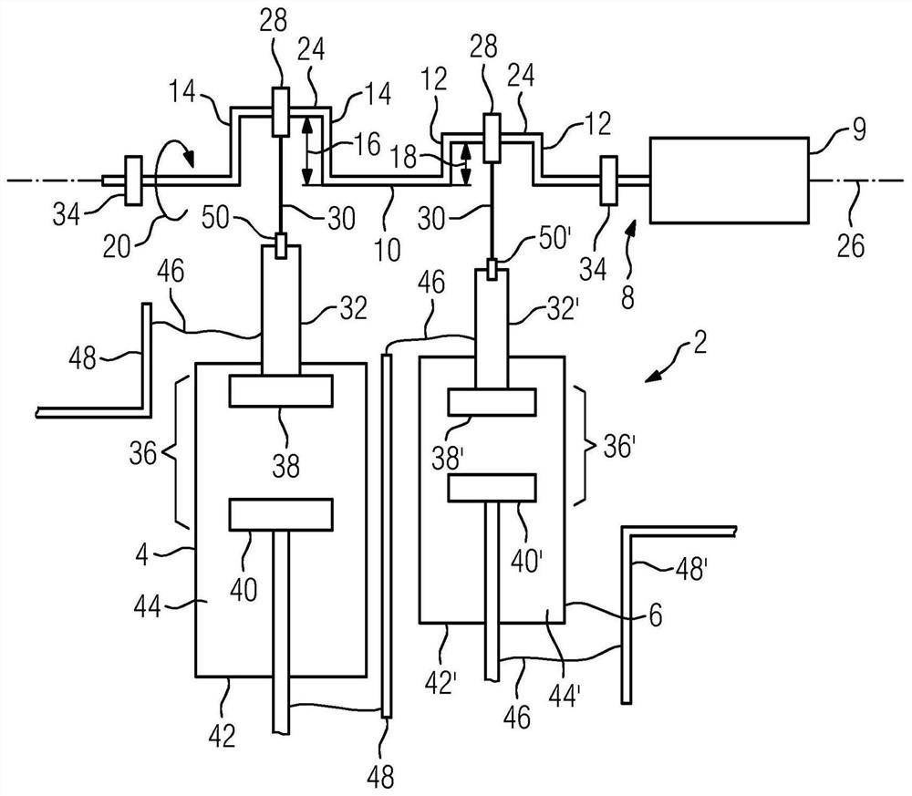
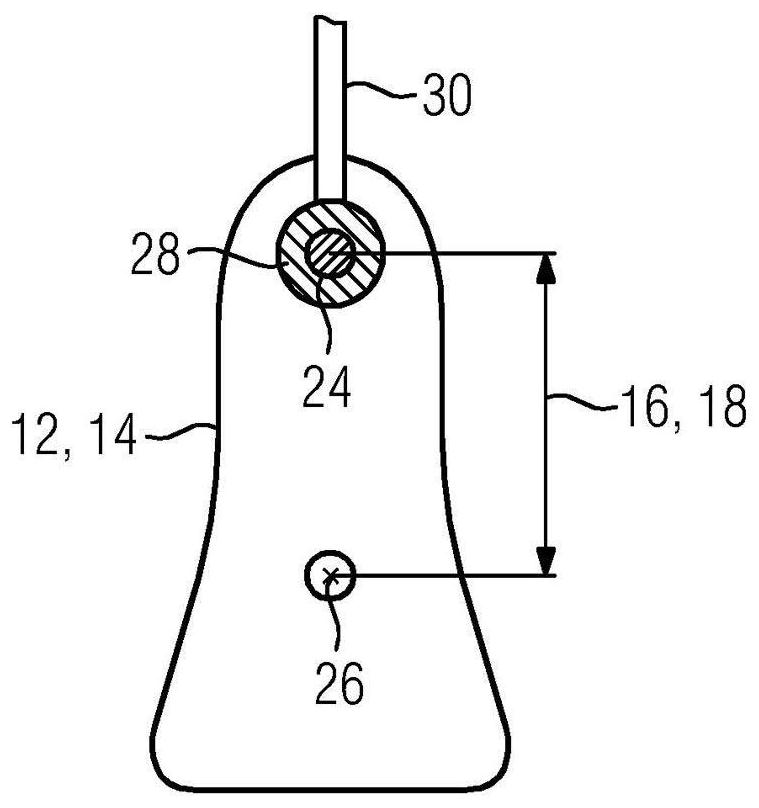
[0024] figure 1 A circuit breaker system 2 is shown in , which on the one hand has a drive system 8 which jointly drives two different circuit breaker units 4 and 6 . The drive system 8 here includes a drive unit 9 and a crankshaft 10 . In this refinement, crankshaft 10 is mounted, for example, on two crankshaft bearings 34 and performs a unidirectional rotational movement along arrow 20 . In this case, the crankshaft 10 has two cranks 12 and 14 which each have different crank strokes 18 and 16 . The term "crank 12" is also understood here to mean a pair of cranks 12 and 12' or 14 and 14' between which a crank pin 24 is arranged. The crankpin 24 extends here parallel to the axis of rotation 26 of the crankshaft 10 . During the rotational movement 20 , the crank pin 24 here describes a circular movement about an axis of rotation 26 . Slide bearings 28 are in turn connected to the crank pin 24 , these slide bearings being in connection with pushrods 30 . A further slide bea...
PUM
 Abstract
Description
Claims
Application Information
 - R&D
- Intellectual Property
- Life Sciences
- Materials
- Tech Scout
- Unparalleled Data Quality
- Higher Quality Content
- 60% Fewer Hallucinations
Browse by: Latest US Patents, China's latest patents, Technical Efficacy Thesaurus, Application Domain, Technology Topic, Popular Technical Reports.
© 2025 PatSnap. All rights reserved.Legal|Privacy policy|Modern Slavery Act Transparency Statement|Sitemap|About US| Contact US: help@patsnap.com