
Dismounting device for insulator binding wire

A technology for dismantling devices and insulators, which is applied in the direction of overhead lines/cable equipment, etc., can solve problems such as affecting work efficiency, hidden dangers of high-altitude operations, and inconvenient disassembly of binding wires, so as to improve the convenience of disassembly and avoid high-altitude operations.

Pending Publication Date: 2022-01-11
ELECTRIC POWER RES INST OF STATE GRID ANHUI ELECTRIC POWER
View PDF0 Cites 0 Cited by
  • Summary
  • Abstract
  • Description
  • Claims
  • Application Information

AI Technical Summary

Problems solved by technology

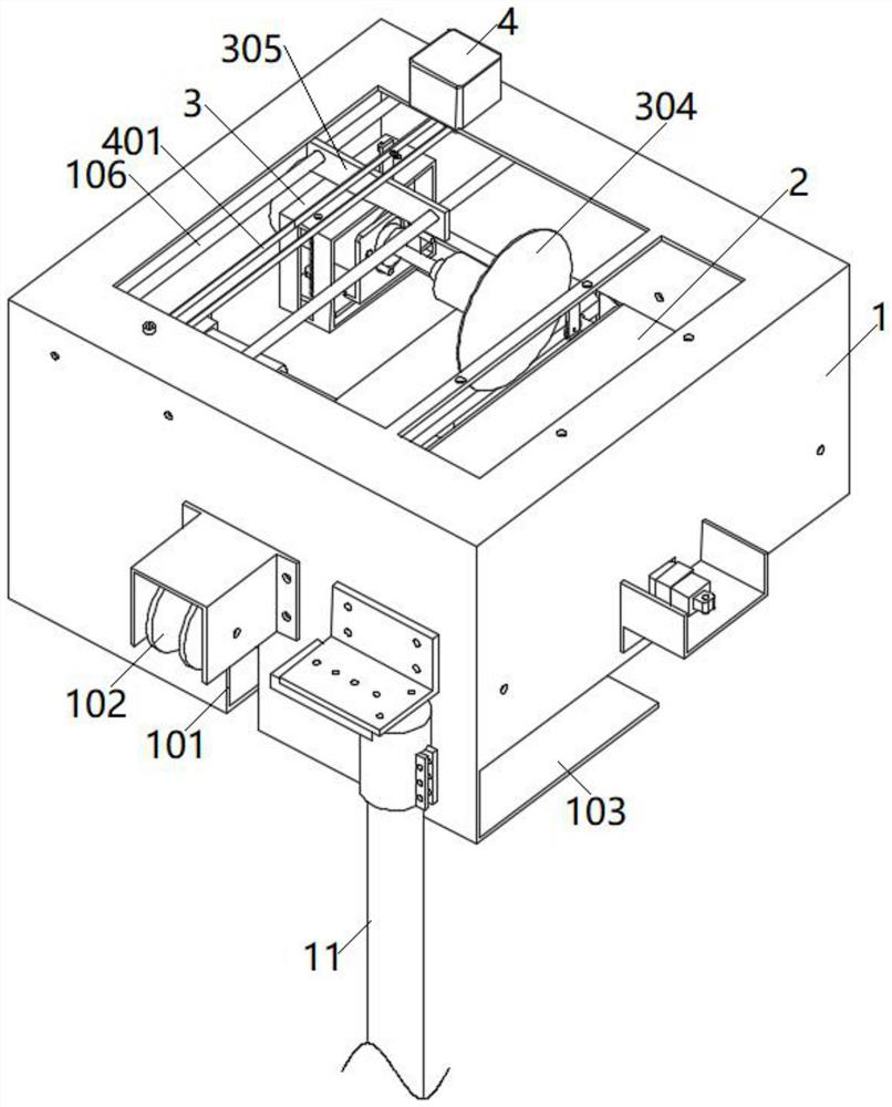
[0003] The purpose of the present invention is to provide a dismantling device for binding wires of insulators, which can realize the disassembly of binding wires, solve the problem that the existing binding wires are inconvenient to disassemble and affect the working efficiency; Personnel can disassemble the binding wire on the ground, which solves the problem of potential safety hazards in existing high-altitude operations

Method used


Image

  • Dismounting device for insulator binding wire
  • Dismounting device for insulator binding wire
  • Dismounting device for insulator binding wire

Examples


Embodiment Construction

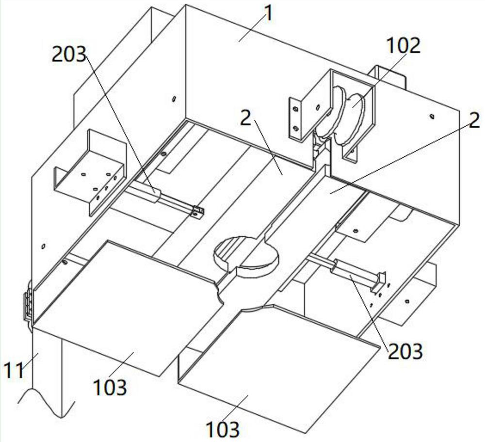
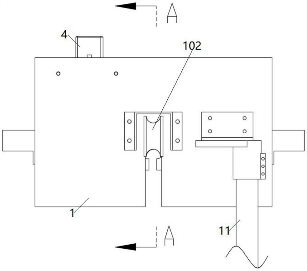
[0026] The following will clearly and completely describe the technical solutions in the embodiments of the present invention with reference to the accompanying drawings in the embodiments of the present invention. Obviously, the described embodiments are only part of the embodiments of the present invention, not all of them. Based on the embodiments of the present invention, all other embodiments obtained by persons of ordinary skill in the art without making creative efforts belong to the protection scope of the present invention.

[0027] see Figure 1-3 As shown, the present invention is a dismantling device for insulator binding wires, including an installation box 1, a clamping rod 2, a wire cutting mechanism and a driving mechanism, and the outer wall of the installation box 1 is connected with a rod 11 by screws. The top wall of the installation box 1 is a hollowed-out structure, which is beneficial to reduce the overall weight of the installation box 1 and improve the...


PUM


Abstract

The invention discloses a dismounting device for an insulator binding wire. The dismounting device comprises a mounting box body, wherein the bottom of the mounting box body is of an open structure; the outer wall of the mounting box body is fixedly connected with an insulating rod; a straight notch is formed in the lower end of the mounting box body; clamping rods are symmetrically arranged on the two sides of the straight notch in the mounting box body; arc-shaped groove channels and arc-shaped clamping grooves are formed in the opposite surfaces of the clamping rods; telescopic mechanisms are symmetrically fixed on the side walls of the mounting box body; the telescopic mechanisms are used for driving the two clamping rods to move oppositely; a wire cutting mechanism is arranged above the clamping rods in the mounting box body; the wire cutting mechanism comprises a mounting frame body which is in sliding connection with the inner wall of the mounting box body; the mounting frame body is driven by a driving mechanism to move in the axial direction of a wire; a motor frame is in sliding connection in the mounting frame body; a motor I is fixed on the motor frame; and an output shaft of the motor I is fixed with a cutting blade. According to the dismounting device, the binding wire can be dismounted, and the problem that the operation efficiency is influenced due to the fact that an existing binding wire is inconvenient to dismount is solved.

Description

technical field [0001] The invention relates to the technical field of electric equipment, in particular to a dismantling device for binding wires of insulators. Background technique [0002] The insulator is installed between the transmission wire and the grounding body such as the cross arm of the utility pole, and is used to insulate and support the power part of the wire. The existing connection and fixation between insulators and conductors includes fixing by wire clips, or binding and fixing by binding wires. In the existing method of fixing wires and insulators with binding wires, when the insulators or binding wires are worn or damaged and need to be replaced, the operator needs to dismantle the binding wires. Since it is necessary to ensure the firmness of the binding during installation, Usually, the number of winding turns of the binding wire is large, which makes it difficult for operators to dismantle it, which makes it very inconvenient to disassemble the bind...

Claims


Application Information

Patent Timeline
IPC IPC(8): B21F11/00H02G1/02
CPCB21F11/00H02G1/02
Inventor 冯玉吴少雷吴凯骆晨王庆军王明戚振彪李君葛明明王志强卞海瑞黄芳胜
Owner ELECTRIC POWER RES INST OF STATE GRID ANHUI ELECTRIC POWER
Learn More