Steel pipe positioning and cutting device

A technology for positioning cutting and steel pipes, applied in the direction of pipe shearing devices, shearing devices, and attachments of shearing machines, etc., can solve the problem of large feed depth of cutters, reduce the cutting depth, improve cutting quality, and improve the use of The effect of longevity

Active Publication Date: 2022-01-11
安徽长江钢铁股份有限公司
View PDF0 Cites 0 Cited by
  • Summary
  • Abstract
  • Description
  • Claims
  • Application Information

AI Technical Summary

Problems solved by technology

[0003] Aiming at the deficiencies of the prior art, the object of the present invention is to provide a positioning cutting device for steel pipes, which solves the problem of large feed depth of the cutter in the prior art

Method used


Image

  • Steel pipe positioning and cutting device
  • Steel pipe positioning and cutting device
  • Steel pipe positioning and cutting device

Examples


Embodiment Construction

[0028] The following will clearly and completely describe the technical solutions in the embodiments of the present invention with reference to the accompanying drawings in the embodiments of the present invention. Obviously, the described embodiments are only some, not all, embodiments of the present invention. Based on the embodiments of the present invention, all other embodiments obtained by persons of ordinary skill in the art without creative efforts fall within the protection scope of the present invention.

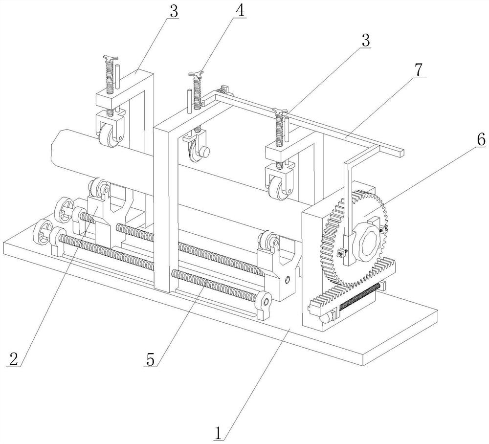
[0029] Such as figure 1 As shown, a steel pipe positioning cutting device includes a base plate 1, the upper end of the base plate 1 is provided with a support mechanism 2, and the support mechanism 2 is used to support the steel pipe to facilitate cutting of the steel pipe;

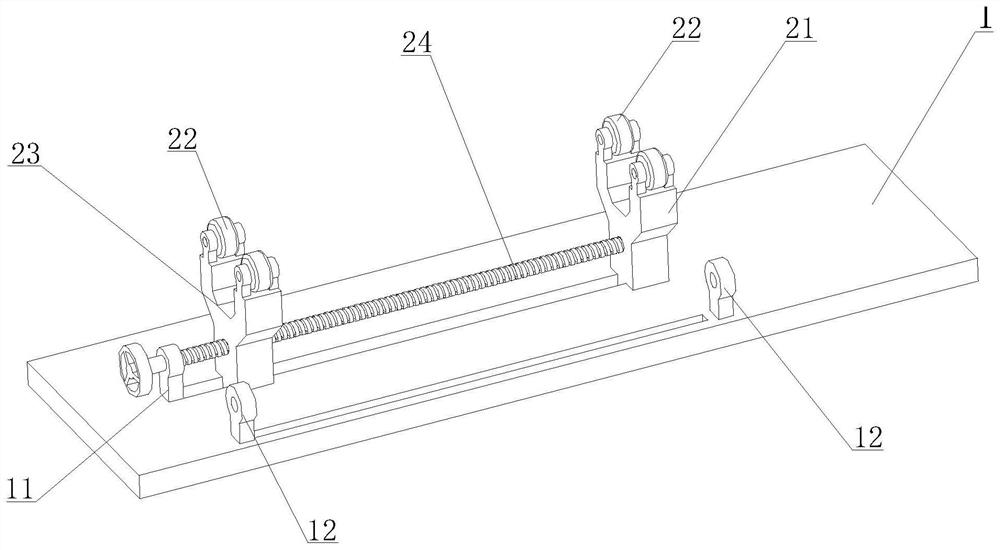
[0030] Such as figure 2 As shown, the upper end of the base plate 1 is provided with a first support plate 21 and a second support plate 23, and the upper ends of the first support base 21 ...


PUM


Abstract

The invention discloses a steel pipe positioning and cutting device, and belongs to the field of steel pipe cutting. The steel pipe positioning and cutting device comprises a supporting mechanism, a pressing mechanism, a rotating mechanism, a cutting mechanism and a limiting mechanism. By arranging the supporting mechanism and the pressing mechanism, a steel pipe only keeps the rotation freedom degree, by arranging the rotating mechanism, the steel pipe is driven to rotate, the cutting action of the cutting mechanism is matched, the steel pipe can rotate in the cutting process, uniform cutting of the outer circle of the steel pipe is achieved, and the cutting quality is improved; meanwhile, the cutting depth of the cutter is effectively reduced, and the service life of the cutter is prolonged; and the limiting mechanism is installed at the upper end of the cutting mechanism to control the cutting time of the cutting mechanism, and the situation that when the steel pipe is not clamped, the cutting mechanism performs cutting action, in the cutting process, the cutter drives the steel pipe to rotate, and the cutting effect is affected is avoided.

Description

technical field [0001] The invention belongs to the field of steel pipe cutting, and in particular relates to a steel pipe positioning cutting device. Background technique [0002] With the continuous development of science and technology, steel pipe cutting is a very common process in daily production. In the prior art, when cutting steel pipes with large diameters, the feed depth of the cutter is large, which makes the wear of the cutter block, affecting the service life of the cutter. Contents of the invention [0003] Aiming at the deficiencies of the prior art, the object of the present invention is to provide a positioning cutting device for steel pipes, which solves the problem of large feed depth of the cutter in the prior art. [0004] The purpose of the present invention can be achieved through the following technical solutions: [0005] A steel pipe positioning cutting device, comprising a bottom plate, the upper end of the bottom plate is provided with a firs...

Claims


Application Information

Patent Timeline
Patent Type & Authority Applications(China)
IPC IPC(8): B23D21/00B23D33/02
CPCB23D21/00B23D33/02
Inventor 查统亮甘强
Owner 安徽长江钢铁股份有限公司
Why Eureka
Try Eureka