
Welding system for two-core wire and DC terminal

A welding system and core wire technology, used in welding equipment, welding/welding/cutting items, connections, etc., can solve problems such as poor position accuracy, inability to weld short wire ends, and inability to weld long wire ends.

Pending Publication Date: 2022-01-11
东莞市东鸿智能科技有限公司
View PDF1 Cites 0 Cited by
  • Summary
  • Abstract
  • Description
  • Claims
  • Application Information

AI Technical Summary

Problems solved by technology

However, this patent also has the following deficiencies: first, it is difficult for the welding mechanism to rise, fall, move left, and right accurately, and the position accuracy is poor; second, the two-core wire head cannot be positioned; third, the long The wire head is welded on the metal connector on the side of the DC terminal, and the short wire head cannot be welded on the metal connector on the rear end of the DC terminal.

Method used


Image

  • Welding system for two-core wire and DC terminal
  • Welding system for two-core wire and DC terminal
  • Welding system for two-core wire and DC terminal

Examples


Embodiment Construction

[0021] The structural principle and working principle of the present invention will be further described in detail below in conjunction with the accompanying drawings.

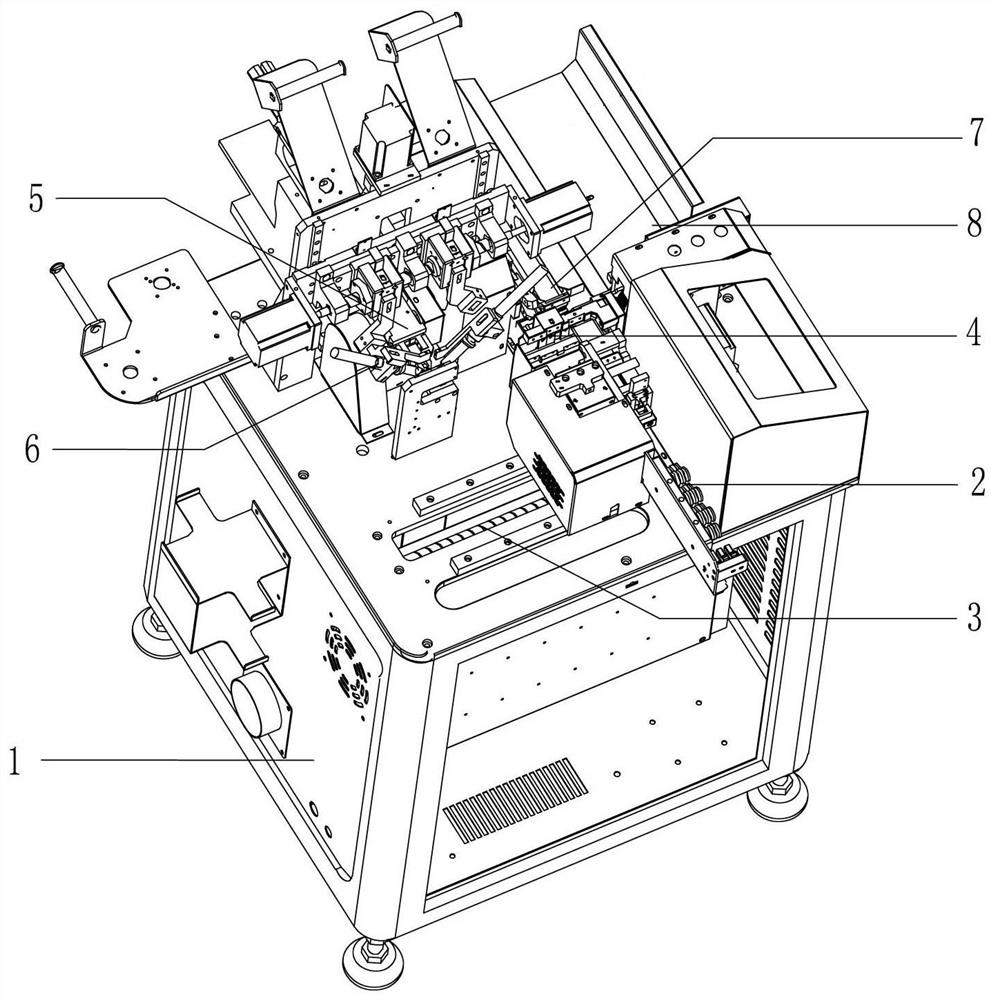
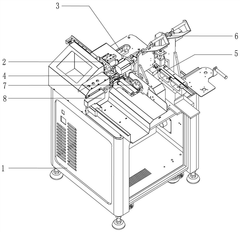
[0022] Such as Figure 1-Figure 2 As shown, it is a fully automatic two-core wire and DC terminal welding and tin bonding machine applying the present invention. The fully automatic two-core wire and DC terminal welding and tin bonding machine includes machine 1 and is installed on machine 1. The above two-core wire feeding device 2, two-core wire translation transmission device 3, two-core wire cutting device 4, DC terminal conveying device 5, welding system 6, tin sticking device 7 and discharge device 8, among which:

[0023] The two-core wire feeding device 2 is used to convey the two-core wire and clamp the two-core wire, and is installed on the two-core wire translation transmission device 3;

[0024] The two-core wire translation transmission device 3 is used to transfer the two-core wire feeding devic...


PUM


Abstract

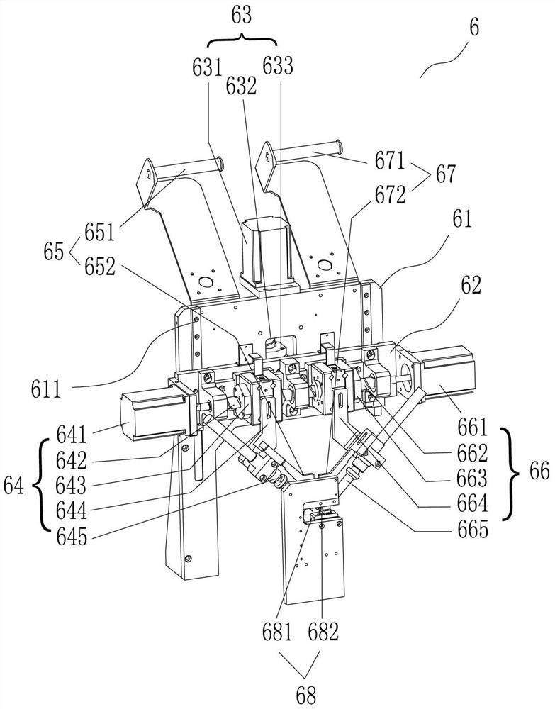
The invention discloses a welding system for a two-core wire and a DC terminal. The welding system comprises a welding rack, a lifting plate, a lifting device, a first welding device, a first tin wire feeding device, a second welding device, a second tin wire feeding device and a two-core wire electric wire end positioning device. The welding rack is provided with a vertical lifting sliding rail, and the lifting plate is installed on the lifting sliding rail in a sliding manner. The lifting device is mounted on the welding rack; the first welding device and the second welding device are both mounted on the lifting plate; and the two-core wire electric wire end positioning device is used for positioning a long electric wire end and a short electric wire end of the two-core wire in the welding process. The welding device can accurately ascend, descend, move leftwards and move rightwards, can position the long electric wire end and the short electric wire end of the two-core wire, can weld the long electric wire end on a metal connecting piece at the side portion of the DC terminal, and can weld the short electric wire end on a metal connecting piece at the rear end of the DC terminal.

Description

technical field [0001] The invention relates to the technical field of DC terminal two-core wire processing equipment, in particular to a welding system for two-core wires and DC terminals. Background technique [0002] DC terminals are widely used in electronic products. There are various types of DC terminals. Each DC terminal usually has two metal contact terminals, and the two metal contact terminals are separated by plastic parts. Such as Figure 7 As shown, it is an existing commonly used DC terminal two-core wire structure, which includes a DC terminal 100 and a two-core wire 200, and the DC terminal 100 includes a first metal contact terminal 101, a plastic part 102 and a second metal contact terminal 103 The plastic part 102 isolates the first metal contact terminal 101 and the second metal contact terminal 102, the connection part 1011 of the first metal contact terminal 101 is located at the rear end of the DC terminal, and the connection part 1021 of the second m...

Claims


Application Information

Patent Timeline
IPC IPC(8): B23K3/00B23K3/06B23K3/08B23K101/36
CPCH01R43/02H01R43/0235H01R43/0263
Inventor 胡红燕
Owner 东莞市东鸿智能科技有限公司
Learn More