Forming cylinder system structure in SLM rapid forming equipment

A technology of system structure and molding equipment, which is applied in the field of metal parts processing, can solve problems such as parts defects and insufficient temperature control of the substrate, and achieve the effects of ensuring accuracy, meeting temperature conditions, and ensuring uniformity

Inactive Publication Date: 2020-06-16
HANGZHOU DIANZI UNIV
View PDF8 Cites 8 Cited by
  • Summary
  • Abstract
  • Description
  • Claims
  • Application Information

AI Technical Summary

Problems solved by technology

Since the molding process of SLM is carried out on the substrate, there are still deficiencies in the thermal stress treatment in China. The temperature control of the entire substrate is not in place, and there are still parts defects caused by large temperature differences in local areas.

Method used


Image

  • Forming cylinder system structure in SLM rapid forming equipment
  • Forming cylinder system structure in SLM rapid forming equipment
  • Forming cylinder system structure in SLM rapid forming equipment

Examples


Embodiment Construction

[0030] The technical solutions of the present invention will be described in further detail below with reference to the accompanying drawings and embodiments.

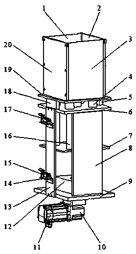
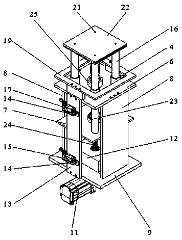
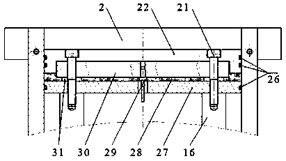
[0031] Such as figure 1 As shown, this embodiment mainly includes: a lifting mechanism, a preheating system structure and a molding cavity structure, wherein:

[0032] The lifting mechanism includes: linear motion bearing 4; rear support plate 5; upper support plate 6; linkage plate 7; side support plate 8; support base plate 9; Position switch fixed plate 13; limit switch support plate 14; lower limit switch 15; guide rod 16; upper limit switch 17; front support plate 18; molding cavity support plate 19; screw 21; base plate 22; linkage plate support Seat 23; leading screw 24; supporting seat 25 on the leading screw; circlip 32; deep groove ball bearing 33; thrust cylindrical roller bearing 34; retaining ring 35, see figure 1 , figure 2 , Figure 5 , Image 6 with Figure 7 .

[0033] Concrete structure: the s...


PUM

PropertyMeasurementUnit
thicknessaaaaaaaaaa

Abstract

The invention discloses a forming cylinder system structure in SLM rapid forming equipment. According to the forming cylinder system structure in the SLM rapid forming equipment, a lifting mechanism is driven by the corresponding servo motor, a ball screw nut pair is driven by a right-angle speed reducer to move, then up-down movement of a preheating system structure is achieved, and the relevantthickness of the powder laying layer is controlled. The preheating system structure heats a base plate through a cast aluminum heating plate, a thermocouple is adopted as a temperature sensor, real-time control over the temperature is achieved, heat insulation silk floss and a heat insulation plate are additionally arranged below the heating plate for relevant heat insulation, and sealing rubber strips are installed on the side edges of the base plate and the heat insulation plate to prevent machined metal powder from falling along a forming cavity. According to the forming cylinder system structure in the SLM rapid forming equipment, the lifting mechanism is used for accurately controlling the thickness of the powder laying layer, the preheating system structure is used for accurately controlling the machining temperature of the metal part, the machining environment of the whole metal part is optimized, and the machining surface quality of the metal part is controlled and improved.

Description

technical field [0001] The invention belongs to the field of metal parts processing, and relates to a device for performing a series of operations such as heating, melting and forming the raw materials of metal parts to be processed. Background technique [0002] Additive manufacturing technology is a new forming technology based on the idea of ​​discrete accumulation forming. At present, there are three kinds of additive manufacturing technologies used to directly manufacture metal parts: selective laser sintering technology (SLS), laser cladding manufacturing technology (LENS) , Metal laser selective melting technology (SLM). Compared with SLS and LENS, the biggest advantage of SLM technology is that it can directly and selectively melt the required metal powder to obtain the required parts. [0003] For SLM, the thickness of the powder layer greatly affects the surface quality of metal moldings. Generally, the thickness of the powder layer in SLM equipment is required to...

Claims


Application Information

Patent Timeline
Patent Type & Authority Applications(China)
IPC IPC(8): B22F3/105B33Y30/00
CPCB33Y30/00B22F3/003B22F10/00B22F12/30B22F10/28B22F12/222B22F12/17Y02P10/25
Inventor 龚友平戚金来杨臣朱自谋刘海强邵惠峰李文欣陈慧鹏彭章明陈国金
Owner HANGZHOU DIANZI UNIV
Why Eureka
Try Eureka