
Spinning roller cart for spinning workshop

A textile roller and trolley technology, applied in trolleys, multi-axis trolleys, trolley accessories, etc., can solve the problems of heavy labor, lumbar muscle strain of operators, troublesome operation, etc., and achieve the effect of reducing the need for human operation

Inactive Publication Date: 2022-01-11
尹希阳
View PDF0 Cites 0 Cited by
  • Summary
  • Abstract
  • Description
  • Claims
  • Application Information

AI Technical Summary

Problems solved by technology

[0002] The existing textile roller trolleys only have a simple frame design. All the textile rollers must be placed before transportation, and the layers of isolation can be manually removed from the shelf after being transported to the designated location. In this way, it is necessary for people to manually move the textile rollers placed in different positions when they are placed and removed from the shelf. The operation is troublesome and the labor load is large. Taller people bend down to carry the textile rollers. After a long time, it is easy to cause lumbar muscle strain on the operators. In order to solve the above problems, a textile roller cart for textile workshops is invented.

Method used


Image

  • Spinning roller cart for spinning workshop
  • Spinning roller cart for spinning workshop
  • Spinning roller cart for spinning workshop

Examples


Embodiment Construction

[0024] The following will clearly and completely describe the technical solutions in the embodiments of the present invention with reference to the accompanying drawings in the embodiments of the present invention. Obviously, the described embodiments are only some, not all, embodiments of the present invention.

[0025] Examples of the described embodiments are shown in the drawings, wherein like or similar reference numerals designate like or similar elements or elements having the same or similar functions throughout. The embodiments described below by referring to the figures are exemplary and are intended to explain the present invention and should not be construed as limiting the present invention.

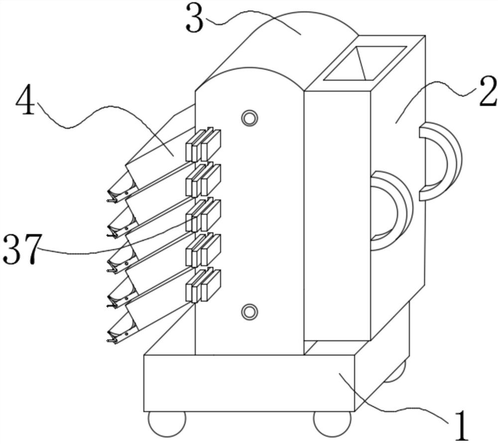
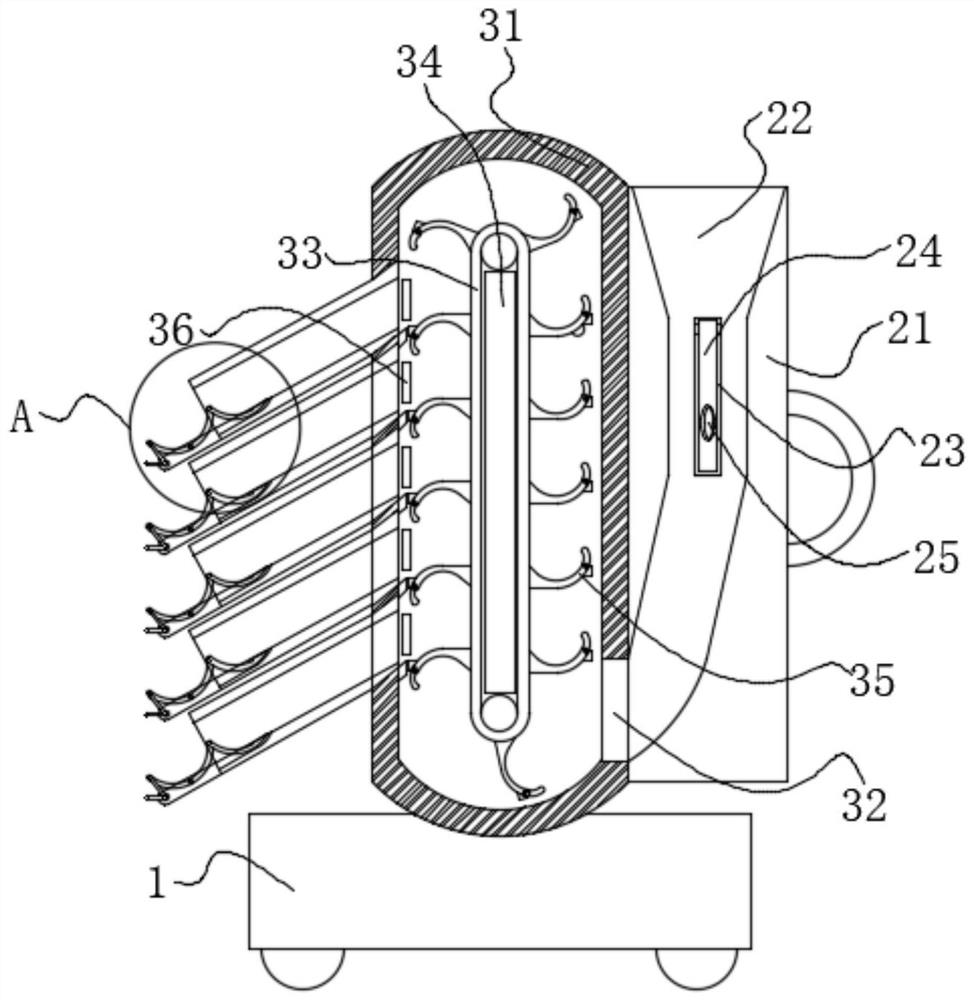
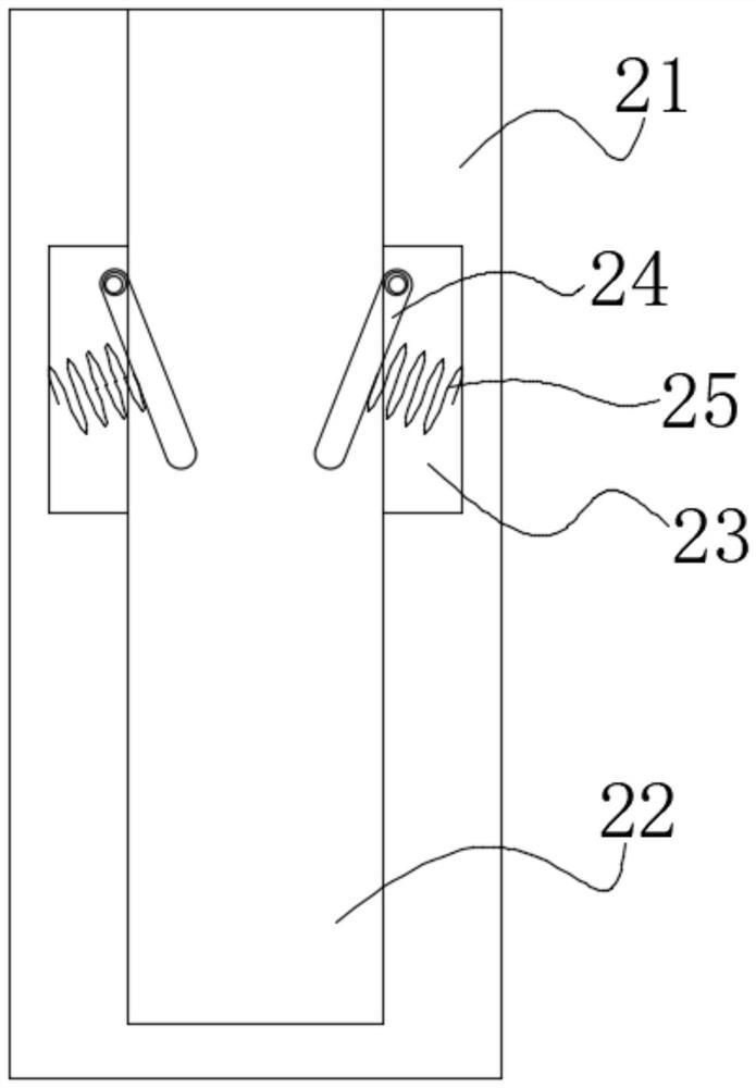
[0026] see Figure 1-7 , the present invention provides a technical solution: a textile roller trolley for a textile workshop, comprising a base 1, a roller loading device 2, a roller row device 3 and a roll connecting device 4, and a roller row device 3 is fixedly installed...


PUM


Abstract

The invention discloses a spinning roller cart for a spinning workshop, and relates to the technical field of spinning equipment. The spinning roller cart for a spinning workshop comprises a base, a roller installing device, a roller arranging device and a roller receiving device, the roller arranging device is fixedly installed on the upper surface of the base, and the roller installing device is fixedly connected to the right side of the roller arranging device. According to the spinning roller cart for a spinning workshop, the roller installing device is arranged, due to the fact that an opening of a flaring channel is large, an operator does not need to adjust the direction of a spinning roller manually and only needs to throw away the spinning roller with hands, many manual operation requirements are reduced, due to the effect of a pressure reduction plate in a flaring channel, the middle of the flaring channel can be narrowed, when the two ends of the spinning roller make contact with the two pressure reduction plates, the two sides of the spinning roller should be too narrow, and the drooping speed of the spinning roller is temporarily reduced, so that the situation that the rollers collide with one another due to too high downward pressing speed and are damaged is prevented, and the rollers can be sequentially arranged in the flaring channel.

Description

technical field [0001] The invention relates to the technical field of textile equipment, in particular to a textile roller trolley for a textile workshop. Background technique [0002] The existing textile roller trolleys only have a simple frame design. All the textile rollers must be placed before transportation, and the layers of isolation can be manually removed from the shelf after being transported to the designated location. In this way, it is necessary for people to manually move the textile rollers placed in different positions when they are placed and removed from the shelf. The operation is troublesome and the labor load is large. Higher people bend down to carry the textile rollers. After a long time, it is easy for the operators to suffer from lumbar muscle strain. In order to solve the above problems, a textile roller cart is invented in a textile workshop. Contents of the invention [0003] Aiming at the deficiencies of the prior art, the invention provide...

Claims


Application Information

Patent Timeline
IPC IPC(8): B62B3/04B62B5/00
CPCB62B3/04B62B5/00
Inventor 尹希阳
Owner 尹希阳
Learn More