Liquid metering and supplying device and supplying method and equipment related to liquid metering and supplying

A supply device and liquid metering technology, applied in the direction of volume measurement and fluid delivery, measuring device, liquid/fluid solid measurement, etc., can solve the problems of tube-type precise continuous batching, continuous metering reaction, inability to provide continuous linear metering output, Difficult to be a stable straight line and other problems, to achieve the effect of convenient overall layout, simple structure and low cost

Pending Publication Date: 2022-01-11
河北兴烨灭菌科技有限公司
0 Cites 0 Cited by

AI-Extracted Technical Summary

Problems solved by technology

Using plug-type and diaphragm-type metering pumps, the actual picture of the PH value curve is wavy and linear, and it is difficult to be a smooth straight line. This is mainly due to the difficulty in controlling the output of reactants by existing metering pumps.
[0006] At present, the existing injection plug t...

Method used

As shown in Figure 2, drive unit comprises the first rotating drive part 8 that is fixed on the frame 1, is driven by the first rotating drive part 8 and can rotate the leading screw 9 on frame 1, and A slide block 10 that is screwed to the lead screw 9. Wherein, the first rotation driving part 8 preferably adopts an existing stepping motor, so as to realize precise control of the rotation angle of the leading screw 9, and the leading screw 9 is connected with the output shaft of the stepping motor, so that the stepping motor can drive the screw. Bar 9 rotates. In this structure, the stepper motor can of course be replaced by a servo motor.
[0084] The t...

Abstract

The invention provides a liquid metering and supplying device and supplying method and equipment related to liquid metering and supplying. The liquid metering and supplying device comprises a liquid inlet header pipe, a liquid outlet header pipe and at least two injection pipelines connected between the liquid inlet header pipe and the liquid outlet header pipe in parallel, and further comprises a rack and injection mechanisms arranged on the rack. Specifically, each injection pipeline comprises a liquid inlet branch pipe and a liquid outlet branch pipe which are connected through a three-way valve, the injection mechanisms and the injection pipelines are arranged in a one-to-one correspondence mode, and each injection mechanism comprises an injector with an inlet and an outlet connected with the three-way valve and a driving unit for driving a piston rod of the injector to slide in a reciprocating mode in the axial direction of the piston rod; the driving unit comprises a first rotation driving part arranged on the rack, a lead screw driven by the first rotation driving part and capable of rotating on the rack, and a sliding block in threaded connection with the lead screw and connected with the piston rod. The liquid metering and supplying device is applied to liquid supply, and continuous, stable, constant-flow, metering and constant-quantity precise output of liquid is facilitated.

Application Domain

Volume measurement and fluid deliveryLiquid material

Technology Topic

Image

  • Liquid metering and supplying device and supplying method and equipment related to liquid metering and supplying
  • Liquid metering and supplying device and supplying method and equipment related to liquid metering and supplying
  • Liquid metering and supplying device and supplying method and equipment related to liquid metering and supplying

Examples

  • Experimental program(1)

Example Embodiment

[0056] It should be noted that, in the case of no conflict, the embodiments of the present invention and the features in the embodiments can be combined with each other.
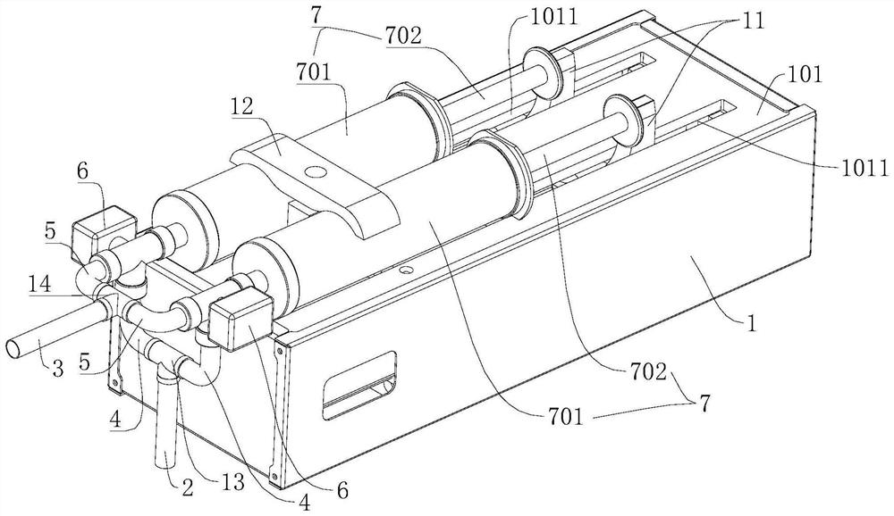
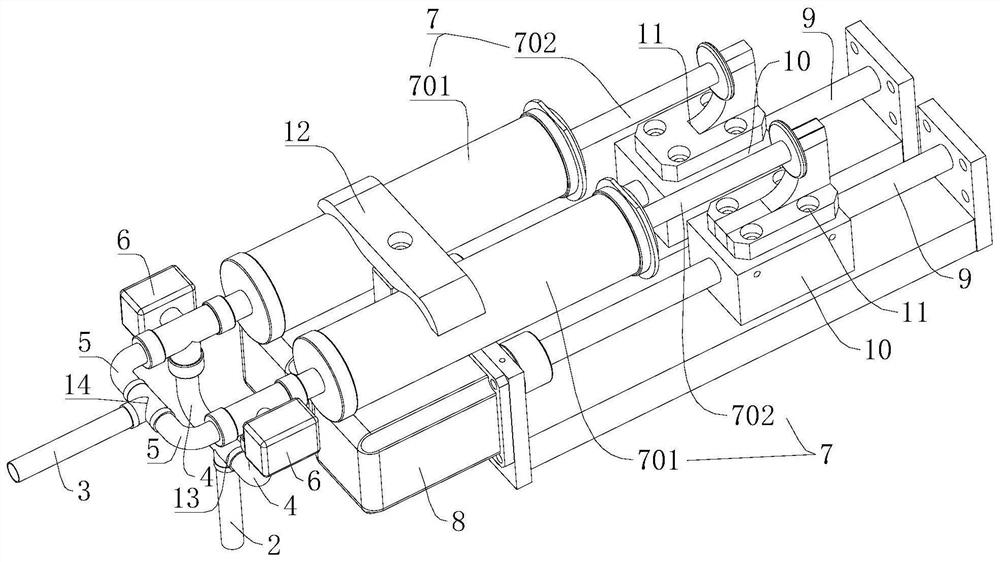
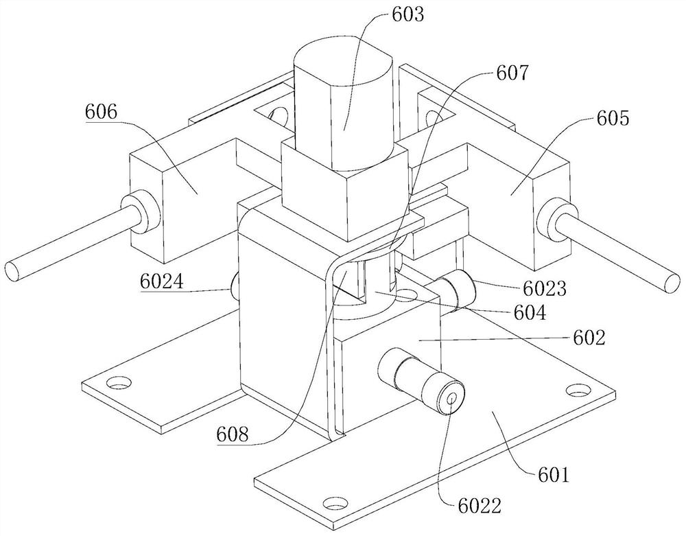
[0057] In the description of the present invention, it should be noted that the orientation or positional relationship indicated by the terms "upper", "lower", "inner", "back" and the like are based on the orientation or positional relationship shown in the drawings, and are only for It is convenient to describe the present invention and simplify the description, but does not indicate or imply that the device or element referred to must have a specific orientation, be constructed and operate in a specific orientation, and thus should not be construed as limiting the present invention. In addition, the terms "first" and "second" are used for descriptive purposes only, and should not be understood as indicating or implying relative importance.
[0058] In addition, in the description of the present invention, unless otherwise clearly defined, the terms "installation", "connection", "connection" and "connector" should be interpreted broadly. For example, it can be a fixed connection, a detachable connection, or an integral connection; it can be a mechanical connection or an electrical connection; it can be a direct connection or an indirect connection through an intermediary; connected. Those of ordinary skill in the art can understand the specific meanings of the above terms in the present invention in combination with specific situations.
[0059] The present invention will be described in detail below with reference to the accompanying drawings and examples.
[0060] This embodiment relates to a liquid metering supply device, such as figure 1 and figure 2 As shown, it includes a liquid inlet main pipe 2, a liquid outlet main pipe 3, and at least two injection pipelines connected between the liquid inlet main pipe 2 and the liquid outlet main pipe 3, and also includes a frame 1, and is located on the frame 1. The injection mechanism on the top, each injection mechanism alternates in turn, and can be fed by the liquid inlet main pipe 2, and can be discharged from the liquid outlet main pipe 3. Cooperating with the control device, the precise measurement of the liquid supply can be realized.
[0061] In order to facilitate a better understanding of this embodiment, the following reference figure 1 and figure 2 Briefly describe the structure of the liquid metering supply device in this embodiment. In this embodiment, there are two injection pipelines, and two injection mechanisms corresponding to the injection pipelines. In addition, the number of injection mechanisms is of course Other numbers are possible, such as three. However, it should be noted that in actual control, before the liquid of the previous injection mechanism is ejected, the next injection mechanism should be prepared for liquid discharge in advance, so as not to affect the continuity of liquid supply.
[0062] In order to facilitate a better understanding of this embodiment, the structure of the frame 1 will be described here first. The frame 1 is the installation carrier for the remaining parts, and it is formed by welding and screwing the plates and profiles. It is convenient to arrange all parts.
[0063] In this embodiment, the frame 1 has an upper mounting plate 101 and a lower mounting plate 102 arranged at intervals up and down, and two relief holes 1011 are provided on the upper mounting plate 101, and the two relief holes 1011 are preferably strip-shaped holes. Its length direction extends along the length direction of the rack 1 .
[0064] like figure 1 and figure 2 As shown, the two injection pipelines communicate with the liquid inlet manifold 2 through the same first valve body 13 , and the two injection pipelines communicate with the liquid outlet manifold 3 through the same second valve body 14 . In this embodiment, both the first valve body 13 and the second valve body 14 are common three-way valves. It should be understood here that when the number of injection pipelines changes, corresponding valve bodies can be used as required to facilitate the liquid inlet from the liquid inlet main pipe 2 and the liquid outlet from the liquid outlet main pipe 3 .
[0065] Specifically, each injection pipeline includes a liquid inlet branch pipe 4 and a liquid outlet branch pipe 5, and the liquid inlet branch pipe 4 and the liquid outlet branch pipe 5 are respectively connected to the first inlet and outlet of the three-way valve 6, and the three-way valve 6 The second inlet is communicated with the inlet and outlet of the syringe 7 described below. The three-way valve 6 described here is preferably an electronic three-way valve, and its structure will be described in detail below, and will not be repeated here.
[0066] still refer to figure 1 and figure 2 As shown, two injection mechanisms are arranged side by side on the frame 1, and the structures of the two injection mechanisms are the same. For the convenience of description, a group of injection mechanisms will be taken as an example below for illustration. It includes a syringe 7 and a driving unit that drives the piston rod 702 of the syringe 7 to reciprocate and slide along its own axial direction. During specific installation, the syringe 7 is arranged on the upper mounting plate 101 via the fixing member 12, the driving unit is arranged on the lower mounting plate 102, and the driving units of each injection mechanism are arranged below the corresponding syringe 7, so as to facilitate the overall arrangement.
[0067] like figure 2 As shown, the drive unit includes a first rotary drive part 8 fixed on the frame 1, a lead screw 9 driven by the first rotary drive part 8 and rotatable on the frame 1, and screwed to the lead screw 9 Linked sliders 10. Wherein, the first rotation driving part 8 preferably adopts an existing stepping motor, so as to realize precise control of the rotation angle of the leading screw 9, and the leading screw 9 is connected with the output shaft of the stepping motor, so that the stepping motor can drive the screw. Bar 9 rotates. In this structure, the stepper motor can of course be replaced by a servo motor.
[0068] Continue to refer to figure 2 As shown, a connecting piece 11 is provided on the slider 10, and the connecting piece 11 is set through the relief hole 1011, and one end of the connecting piece 11 is fixed on the sliding block 10, and the other end is connected to the piston rod 702, so that the The slider 10 slides along the axial direction of the lead screw 9 to drive the piston rod 702 to reciprocate.
[0069] In order to facilitate sliding of the slider 10 , a guide mechanism is provided between the frame 1 and the slider 10 for guiding the slider 10 to slide axially along the lead screw 9 . Specifically, the guiding mechanism may include a guiding groove formed on the lower mounting plate 102, and a guiding block provided on the slider 10, and the guiding block is embedded in the guiding groove. With such arrangement, when the lead screw 9 rotates, the slide block 10 can slide axially of the lead screw 9 under the guidance of the guide mechanism under the constraint of the guide mechanism.
[0070] Next refer to Figure 3 to Figure 11 The structure of the three-way valve 6 is described. The three-way valve 6 includes a bracket 601 , a valve body 602 disposed on the bracket 601 , a second rotation driving part 603 , and a valve core 604 disposed in the valve body 602 .
[0071] Wherein, the structure of bracket 601 can be as Figure 5 As shown in , it is formed by bending a plate material, and mainly includes a bottom plate 6011, a first vertical plate 6012, a second vertical plate 6013 and a third vertical plate 6014 formed by bending the edge of the bottom plate 6011 upward.
[0072] Specifically, the bottom plate 6011 is formed with mounting holes for mounting on an external carrier, and mounting holes for mounting the valve body 602 . Mounting holes for mounting the first position detection switch 605 and the second position detection switch 606 are respectively formed on the first vertical plate 6012 and the second vertical plate 6013 . An inwardly bent flange 60141 is formed on the upper part of the third vertical plate 6014 , and an installation hole for installing the second rotation driving part 603 is opened on the flange 60141 .
[0073] The structure of the valve body 602 can be as Image 6 As shown in , a cylindrical cavity 6021 is formed in the valve body 602, and a first channel 6022, a second channel 6023 and a third channel 6024 communicating with the cavity 6021 are also formed, and compared to the communication cavity 6021 One end, the other end of the first channel 6022 is the first inlet, which communicates with the aforementioned liquid inlet pipe, the other end of the second channel 6023 is the second inlet, which communicates with the inlet and outlet of the syringe 7, and the other end of the third channel 6024 One end is an outlet, which communicates with the liquid outlet branch pipe 5 . Preferably, the first channel 6022 and the third channel 6024 are arranged coaxially, and the second channel 6023 is arranged orthogonal to the first channel 6022 and the third channel 6024 .
[0074] The second rotation driving part 603 is arranged on the bracket 601, which preferably adopts an existing motor, and the spool 604 is connected to the output shaft of the motor. In this embodiment, the motor is preferably a stepper motor or a servo motor.
[0075] The lower part of the valve core 604 is located in the cavity 6021 , which is connected to the power output end of the second rotation driving part 603 and can be driven by the second rotation driving part 603 to rotate. Specifically, the valve core 604 is integrally formed by a core body 6041 , a connecting plate 6042 and an adapter piece 608 arranged sequentially from bottom to top.
[0076] Wherein, the core body 6041 is cylindrical, which matches the shape of the cavity 6021 in the valve body 602 mentioned above, and is inserted into the cavity body 6021 . An L-shaped communication channel 60411 is formed in the core body 6041 . The connecting plate 6042 is placed on the outside of the cavity 6021, and the connecting block 6043 is provided with a connecting hole for connecting with the output shaft of the motor.
[0077] In order to ensure the reliable rotation of the core body 6041, in this embodiment, as Figure 10 As shown, the adapter piece 608 is covered on the adapter block 6043 . The cross-sectional shape of the adapter piece 608 is an inverted U shape, and a D-shaped hole is opened on the upper part of the adapter piece 608 . The rotating shaft passes through the D-shaped hole and is connected with the connecting hole on the adapter block 6043, thereby ensuring that the core 6041 rotates with the rotating shaft of the motor.
[0078] The arrangement of the above structure makes the spool 604 rotatable under the driving of the motor, so that the first passage 6022 and the second passage 6023 have a communication state through the communication passage 60411, or a closed state closed by the spool 604, and The second passage 6023 and the third passage 6024 are made to have a communication state via the communication passage 60411 , or a closed state where they are closed by the spool 604 .
[0079] As in this embodiment, when the first channel 6022 and the second channel 6023 are connected through the communication channel 60411, the second channel 6023 and the third channel 6024 are in the closed state, while the second channel 6023 and the third channel 6024 are connected through the communication channel 60411 When connected, the first communication channel 60411 and the second communication channel 60411 are in a closed state.
[0080]In order to facilitate accurate control, a first position detection mechanism and a second position detection mechanism are also provided on the bracket 601 for accurately judging the communication status of each channel. Wherein, both the first position detection mechanism and the second position detection mechanism can adopt existing structures. Specifically in this embodiment, the first position detection mechanism is installed on the first vertical plate 6012 , and the second position detection mechanism is installed on the second vertical plate 6013 .
[0081] In addition, a position detecting member 607 is sheathed on the rotating shaft of the motor. In this embodiment, the position detection member 607 adopts a plate structure, and a D-shaped hole is formed on the position detection mechanism, so that the position detection mechanism can rotate with the rotating shaft of the motor. like Figure 9 As shown, the position detection mechanism also has a protruding detection piece, and the above-mentioned first position detection mechanism and second position detection mechanism can be used to detect the position of the detection piece to judge the communication status of each channel.
[0082] Specifically, when the first position detection mechanism does not detect the detection piece, it can be considered that the spool 604 is not at the initial position, and the control device issues a control command to drive the motor to drive the spool 604 to rotate counterclockwise. When detected by a position detection mechanism, the spool 604 reaches the initial position, and the first passage 6022 and the second passage 6023 communicate through the communication passage 60411 .
[0083] When it is necessary to switch the communication state of the channel in the valve body 602, the control device sends a control command to make the motor drive the valve core 604 to rotate clockwise. When the second position detection mechanism detects the detection piece, the motor stops rotating. At this time, the second The passage 6023 and the third passage 6024 communicate via the communication passage 60411 .
[0084] The three-way valve 6 with the above structure is used to control the flow direction of the liquid. The valve body 602 can be made of polytetrafluoroethylene, which has the advantages of good sealing performance and chemical corrosion resistance. Two position detection switches are used to accurately control the conversion position of the spool 604, which can realize accurate and fast switching, so it can prevent the fluctuation of the liquid flow on each interface caused by the conversion of the spool 604, and will not cause significant pressure on each interface. At the same time, it provides the necessary conditions for the realization of automation and intelligence.
[0085] Therefore, the three-way valve 6 is especially suitable for precise liquid synthesis occasions requiring very high flow accuracy, and it can also be used for continuous liquid precise quasi-synthesis occasions by using more than two three-way valves 6 for cooperative control.
[0086] In the liquid metering and supplying device of the present invention, according to the required flow rate, the control device can send corresponding high-speed pulse signals to control the rotation of two stepping motors or servo motors according to the logic of the program, and the stepping motors or servo motors drive the screw rod 9 Drive the two groups of injection mechanisms to enter and discharge liquid, and at the same time, the control device controls the action of the spools 604 of the two three-way valves 6 according to the program logic to cooperate with the state transition of liquid discharge and liquid intake, so as to realize the alternate work of the two syringes 7 and It can ensure that the output volume of the two syringes 7 is stable when they alternate.
[0087] When the liquid is in, the three-way valve 6 is connected to the liquid inlet main pipe 2 and the syringe 7, and the stepping motor or the servo motor reverses to drive the syringe 7 to enter the liquid; when the liquid is discharged, the three-way valve 6 is connected to the liquid outlet main pipe 3 and the syringe 7 , the stepping motor or the servo motor rotate forward to drive the syringe 7 to discharge liquid.
[0088] When the two injectors 7 work alternately, the two three-way valves 6 are all connected to the liquid outlet main pipe 3, the last injector 7 decelerates, and the next injector 7 accelerates simultaneously, forming complementarity. When the speed of the stepping motor or servo motor of the last syringe 7 returns to zero, the speed of the motor of the next syringe 7 reaches the target value. At this time, switch the three-way valve 6 of the previous syringe 7, connect the liquid inlet pipe, and start the liquid inlet process .
[0089] In this way, the continuity, stability, and constant flow rate of the output of the liquid metering supply device can be guaranteed, and the output flow rate is not affected by external pressure. The two syringes 7 work alternately in this way, which is conducive to making the liquid continuous, stable, constant flow, and constant volume. The precise output can reach the measurement accuracy requirement of 0.005%, so as to achieve the purpose of linear measurement output.
[0090] The liquid metering and supplying device of this embodiment can be used to measure and transport high viscosity, high temperature, high melting point liquid, liquid gas, foaming medium, suspension by selecting the main material of the syringe 7, such as glass, ceramics, engineering plastics, stainless steel, etc. , molten liquid and corrosive, abrasive, highly toxic and radioactive media.
[0091] When the liquid metering and supplying device is used, the control device can also be connected with the display device and the input device, and the input device inputs the required liquid discharge speed, and the display device displays liquid-related information such as the liquid discharge speed.
[0092] Table 1 shows the performance comparison between the liquid metering and supplying device of this embodiment and existing plunger pumps and diaphragm pumps.
[0093] Table 1:
[0094]
[0095] At the same time, this embodiment also relates to a device related to liquid metering supply, including the above liquid metering supply device, and the device is a hypochlorous acid synthesizer, a continuous generator of drinking sterilized water for livestock and poultry breeding, and a liquid phase continuous biochemical synthesizer , Liquid-phase pipeline-type intelligent neutralization reactor, liquid-phase pipeline-type intelligent continuous mixer, liquid-phase intelligent batching device, liquid-phase intelligent continuous dosing device, liquid-phase automatic micro-volume filling device, liquid beverage intelligent continuous deployment and sterilization Equipment, intelligent inactivation equipment for fermentation liquid, intelligent continuous modulation equipment for wine, intelligent continuous synthesis equipment for washing liquid, intelligent continuous synthesis equipment for lubricating oil, intelligent continuous blending equipment for edible oil, breeding microorganism control and disinfection equipment, and livestock and poultry breeding microbial sterilization , nitrogen fixation, carbon fixation and emission reduction equipment.
[0096] At the same time, this embodiment also relates to a liquid supply method, in which at least two injection mechanisms alternately make the liquid flow through the liquid inlet main pipe 2 to the liquid outlet main pipe 3;
[0097] Each injection mechanism uses the first rotating drive part 8 to drive the lead screw 9 to rotate forward or reverse, so that the slider 10 screwed to the lead screw 9 moves back and forth along the axial direction of the lead screw 9, and the slider 10 drives the syringe 7 The piston rod 702 slides synchronously, so that the liquid can first enter the tube body 701 of the syringe 7 through the liquid inlet manifold 2, and then the liquid in the tube body 701 flows to the liquid outlet manifold 3.
[0098] It should be noted here that in actual control, before the liquid of the previous injection mechanism is ejected, the next injection mechanism should be ready to discharge liquid in advance, so as not to affect the continuity of liquid supply.
[0099] Compared with the prior art, the liquid supply method and the equipment related to the liquid metering supply of the present invention have the same beneficial effects as the aforementioned liquid metering supply device, and will not be repeated here.
[0100] The above descriptions are only preferred embodiments of the present invention, and are not intended to limit the present invention. Any modifications, equivalent replacements, improvements, etc. made within the spirit and principles of the present invention shall be included in the scope of the present invention. within the scope of protection.

PUM

no PUM

Description & Claims & Application Information

We can also present the details of the Description, Claims and Application information to help users get a comprehensive understanding of the technical details of the patent, such as background art, summary of invention, brief description of drawings, description of embodiments, and other original content. On the other hand, users can also determine the specific scope of protection of the technology through the list of claims; as well as understand the changes in the life cycle of the technology with the presentation of the patent timeline. Login to view more.

Similar technology patents

Double split wire spacer mounting tool

Owner:云南送变电工程有限公司

Nozzle of intelligent pedestal pan

PendingCN111456180AReduced installation space occupiedEasy to arrangeWater closetsLavatory sanitoryEngineeringMechanics
Owner:ZHEJIANG TEJJER INTELLIGENT SANITARY WARE

Classification and recommendation of technical efficacy words

  • Easy to arrange
  • Save space

Industrial truck comprising two load carriages

InactiveUS20110120807A1Easy to arrangeLow loadLifting devicesTruckEngineering
Owner:BT PROD

Liquid pump with axial thrust washer

ActiveUS20130121808A1Simple structural designEasy to arrangePump componentsPumpsAerospace engineeringAxial thrust
Owner:ROBERT BOSCH GMBH
Why Eureka
Try Eureka