Generator rotor collector ring carbon brush constant-pressure spring pressure detection device

A generator rotor and constant pressure spring technology, applied in measuring devices, elastic testing, mechanical parts testing, etc., can solve problems such as difficult to reflect spring pressure results, uneven technical ability and experience, and measurement result errors , to achieve the effect of reducing labor intensity, avoiding equipment damage accidents, and reducing measurement errors

Pending Publication Date: 2022-01-11
国能宁东第一发电有限公司
View PDF0 Cites 3 Cited by
  • Summary
  • Abstract
  • Description
  • Claims
  • Application Information

AI Technical Summary

Problems solved by technology

These methods have certain shortcomings. Manual activity experience inspection, due to the change of inspectors and uneven technical ability and experience, cannot effectively monitor the defect of weakened spring pressure, which leads to frequent occurrence of collector ring fire incidents;
[0006] However, the measurement using a spring scale is relatively accurate, but it is necessary to manually measure and record each carbon brush, which is time-consuming, laborious, and inefficient, and because the constant pressure spring is not in the working position during measurement, there is a certain error in the measurement results, which is also difficult to reflect. spring pressure result

Method used


Image

  • Generator rotor collector ring carbon brush constant-pressure spring pressure detection device
  • Generator rotor collector ring carbon brush constant-pressure spring pressure detection device
  • Generator rotor collector ring carbon brush constant-pressure spring pressure detection device

Examples


Embodiment Construction

[0028] Below in conjunction with specific embodiment, further illustrate the present invention. It should be understood that these examples are only used to illustrate the present invention and are not intended to limit the scope of the present invention. In addition, it should be understood that after reading the content taught by the present invention, those skilled in the art may make various changes or modifications to the present invention, and these equivalent forms also fall within the scope defined in the present application.

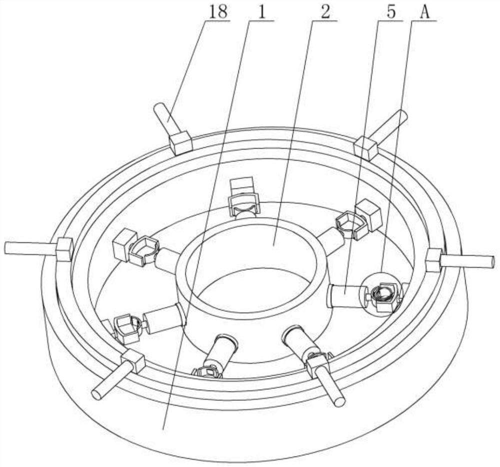
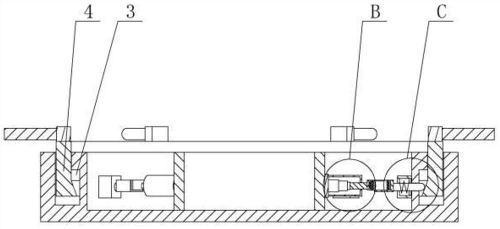
[0029] The present invention is a generator rotor collector ring carbon brush constant pressure spring pressure detection device. The main structure includes a base 1 and a control system. The base 1 is a cylindrical structure. The control system can be selected from the market and belongs to the prior art. , do not go into details here, the center of the base 1 is provided with a limit ring 2, through which the limit ring 2 simulates the collec...


PUM


Abstract

The invention discloses a generator rotor collector ring carbon brush constant-pressure spring pressure detection device, and mainly relates to the field of generator detection equipment. The device comprises a base and a control system, wherein a limiting ring is arranged at the center of the base, a detection body is arranged between the outer wall of the limiting ring and the inner side wall of the base, an annular sliding groove is formed in an outer wall plate of the base, a driving ring is arranged in the sliding groove, the outer side of the driving ring is in threaded connection with the wall of the sliding groove, the section of the side, close to the limiting ring, of the sliding groove is a step face, and the bottom part of the side, close to the limiting ring, of the driving ring is an inverted-cone-shaped section. The device has the beneficial effects that manual operation measurement is omitted, the spring pressure measurement efficiency is improved, the labor intensity of personnel is reduced, measurement can be carried out in a simulated use state, the measurement error is reduced, the degradation state of a carbon brush can be found as early as possible, and equipment damage accidents are avoided.

Description

technical field [0001] The invention relates to the field of generator detection equipment, in particular to a generator rotor collector ring carbon brush constant pressure spring pressure detection device. Background technique [0002] The generator rotor collector ring is a metal ring fixed on the generator rotor, which can rotate with the rotor at high speed, and the carbon brush is installed on the brush holder of the fixed part of the equipment, which is made of carbon blocks and is also called The brush is pressed with a spring on the upper end, contacts the collector ring through the spring pressure, and inputs current to the rotor winding through the wire connected to the head of the carbon brush, forming magnetic poles on the generator rotor, cutting the generator stator winding and inductively generating electricity. ; The working effect of the brush holder and collector ring system mainly depends on the pressure of the constant pressure spring on the carbon brush....

Claims


Application Information

Patent Timeline
Patent Type & Authority Applications(China)
IPC IPC(8): G01M13/00G01M5/00G01L5/00
CPCG01M13/00G01M5/005G01L5/0057
Inventor 王晓强
Owner 国能宁东第一发电有限公司
Why Eureka
Try Eureka