Environment-friendly wood structure building automatic fire fighting device

A technology of building automatic and fire-fighting devices, which is applied in fire rescue and other directions, can solve the problems of inaccessible water flow, lack of automatic and accurate positioning of fire sources, inconvenient use, etc., and achieve the effect of achieving connectivity

Inactive Publication Date: 2022-01-14
南京工业大学建筑设计研究院有限公司
View PDF9 Cites 1 Cited by
  • Summary
  • Abstract
  • Description
  • Claims
  • Application Information

AI Technical Summary

Problems solved by technology

[0006] The purpose of the present invention is: in order to solve the existing automatic fire sprinkler, in the process of use, there is no function of automatically and accurately locating the fire source, the disadvantage of inconvenient use, and the function of not having the function of pressurizing the water, the distance is relatively small For the problem that the water flow cannot be reached in a long distance, the present invention provides an environment-friendly automatic fire-fighting device for wooden structures

Method used


Image

  • Environment-friendly wood structure building automatic fire fighting device
  • Environment-friendly wood structure building automatic fire fighting device
  • Environment-friendly wood structure building automatic fire fighting device

Examples


Embodiment 1

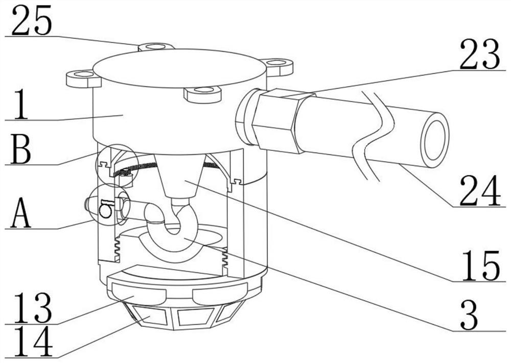
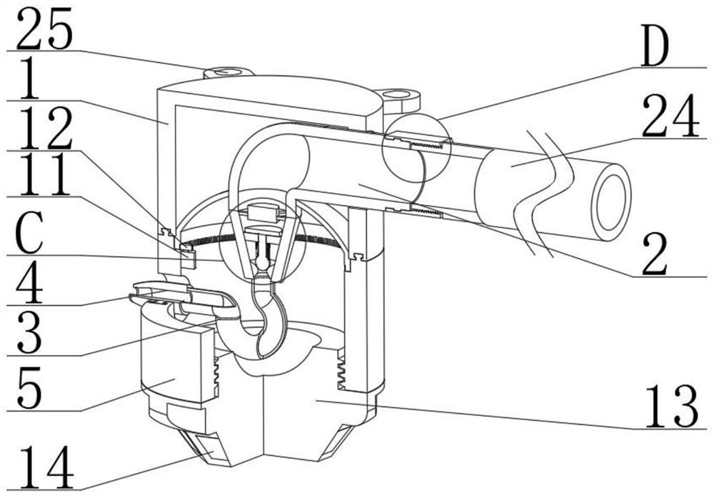
[0031] see figure 2 , 4 And 5, an environment-friendly automatic fire-fighting device for wooden structures, comprising an upper tank body 1, the inside of the upper tank body 1 is fixedly connected with a connecting pipe 2, one end of the connecting pipe 2 is fixedly connected with a pressurized pipe 15, and the pressurized pipe 15 The bottom end of the upper tank body 1 is fixedly connected with a flexible pipe 3, and the pressurized tube 15 is a funnel-shaped pipe with a large opening diameter at the upper end and a smaller opening diameter at the lower end. A through hole is opened, the inside of the through hole is movably connected with the nozzle 4, the other end of the hose 3 is fixedly connected with the nozzle 4, the inside of the lower tank 5 is movably connected with the first gear 6, one side of the nozzle 4 is connected with the first gear 6 is fixedly connected, the inner side of the lower tank body 5 is fixedly installed with a first motor 7, and one end of t...

Embodiment 2

[0034] see image 3 and 6 , this embodiment is further optimized on the basis of Embodiment 1, specifically, a first support frame 16 is fixedly connected to the inside of the connecting pipe 2, and an electromagnet 17 is fixedly connected to one side of the first support frame 16.

[0035] Specifically, the inner side of the pressurizing tube 15 is fixedly connected with a sealing ring 18 and a second support frame 19, the inside of the second support frame 19 is penetrated and movably connected with a sealing column 20, and the top end of the sealing column 20 is fixedly connected with an iron plate 21, Iron plate 21 is matched with electromagnet 17.

[0036] Specifically, a spring 22 is fixedly connected to one side of the sealing column 20 , and a second support frame 19 is fixedly connected to the top end of the spring 22 .

[0037] In this embodiment, the electromagnet 17 can be fixed by the first support frame 16, the sealing column 20 can be supported by the second s...

Embodiment 3

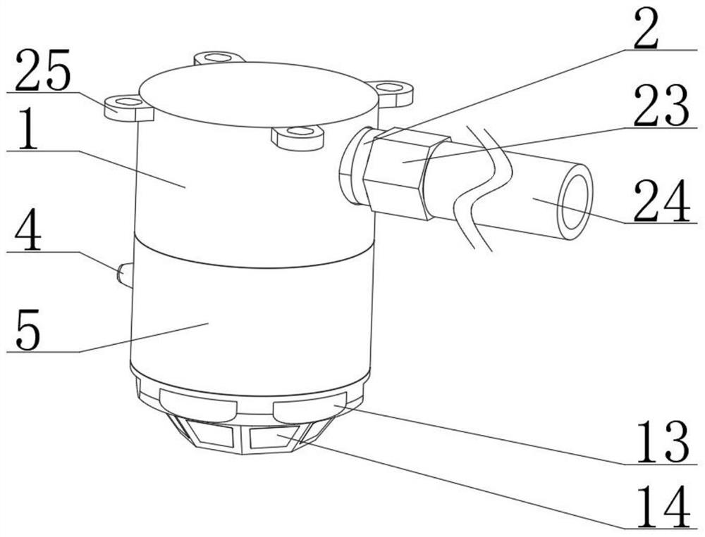
[0039] see figure 1 and 7 , the present embodiment is optimized as follows on the basis of example 1 or example 2, specifically, the upper end side of the connecting pipe 2 is movably connected with a connecting ring 23, and the inner side of the connecting ring 23 is movably connected with a water supply pipe 24, and the connecting ring 23 is compatible with water supply pipe 24.

[0040] Specifically, a plurality of mounting plates 25 are fixedly connected to the upper surface of the upper tank body 1 , and the plurality of mounting plates 25 are distributed in an annular array.

[0041]In this embodiment, the connection between the connecting pipe 2 and the water supply pipe 24 can be realized through the matching of the connecting ring 23 and the water supply pipe 24, and then the communication of the external water source can be realized. Install.

[0042] To sum up: the present invention can detect whether there is high temperature in multiple directions in the area b...


PUM


Abstract

The invention discloses an environment-friendly wood structure building automatic fire-fighting device, and relates to the technical field of fire-fighting devices. The environment-friendly wood structure building automatic fire-fighting device comprises an upper tank body, wherein a connecting pipe is fixedly connected to the interior of the upper tank body; a pressurizing pipe is fixedly connected to one end of the connecting pipe; a hose is fixedly connected to the bottom end of the pressurizing pipe; a lower tank body is movably connected to the bottom end of the upper tank body; a through hole is formed in one side of the lower tank body; a spray head is movably connected to the interior of the through hole; the other end of the hose is fixedly connected with the spray head; and a first gear is movably connected to the interior of the lower tank body. A detector is matched with a plurality of detection sensors at the bottom end of the detector, so that whether high temperature exists in multiple directions of an area can be detected, the high temperature can be positioned, and a second motor can drive a second gear to be matched with a tooth groove, so that the lower tank body can rotate, and the connecting pipe can be fixedly supported through a fixing frame.

Description

technical field [0001] The invention relates to the technical field of fire-fighting devices, in particular to an environment-friendly automatic fire-fighting device for wooden structures. Background technique [0002] The automatic sprinkler fire extinguishing device is a device that can automatically spray water to extinguish the fire. The existing sprinkler device cannot quickly locate and perform the function of spraying water, and the automatic fire protection effect is not good during use. [0003] In the Chinese utility model patent application number: CN201921035998.3, an automatic fire sprinkler device is disclosed, which includes a detection box and a mounting plate installed on the surface of the wall. The detection box and the mounting plate are made through integrated processing. Smoke inlets are opened around the outer surface of the test box, and a water supply main pipe is installed inside the test box. The fire automatic sprinkler device also has the disadv...

Claims


Application Information

Patent Timeline
Patent Type & Authority Applications(China)
IPC IPC(8): A62C31/00A62C31/28A62C37/40
CPCA62C31/005A62C31/28A62C37/40A62C99/0072
Inventor 张浩杨大富李毅过妅庞恺李晗
Owner 南京工业大学建筑设计研究院有限公司
Why Eureka
Try Eureka