
Optical lens ink coating device

An optical lens and ink coating technology, which is applied to the device and coating of the surface coating liquid, can solve the problems of uneven coating and low work efficiency, and achieve the effect of improving precision and reducing the emission of peculiar smell

Active Publication Date: 2022-01-14
上饶市桐宇光电科技有限公司
View PDF7 Cites 0 Cited by
  • Summary
  • Abstract
  • Description
  • Claims
  • Application Information

AI Technical Summary

Problems solved by technology

[0005] In order to overcome the shortcomings of uneven smearing and low work efficiency when smearing optical lenses, the technical problem of the present invention is to provide a faster and more uniform smearing device. When smearing optical lenses, the paint is applied evenly and the work efficiency High optical lens inking device

Method used


Image

  • Optical lens ink coating device
  • Optical lens ink coating device
  • Optical lens ink coating device

Examples


Embodiment 1

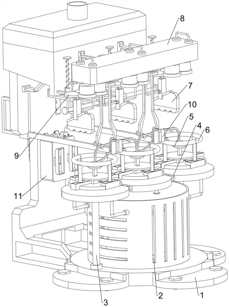
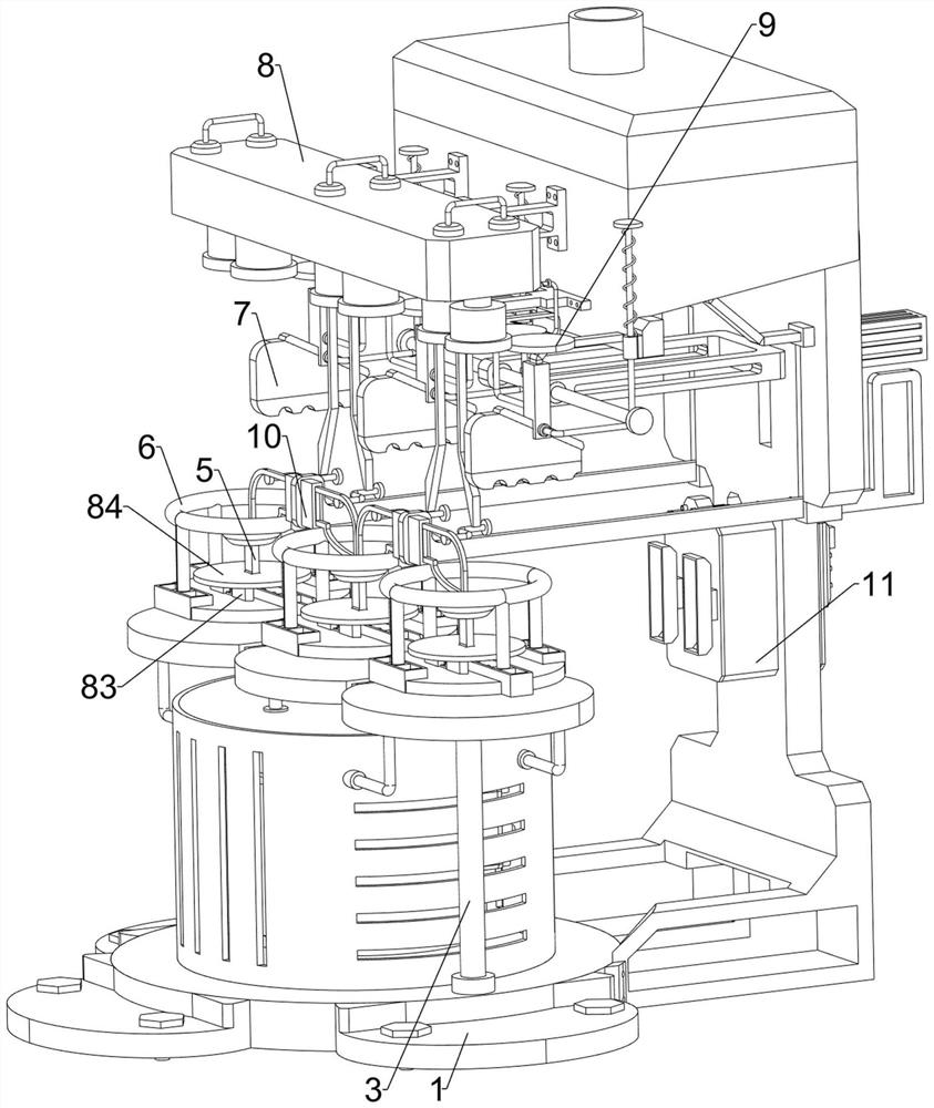
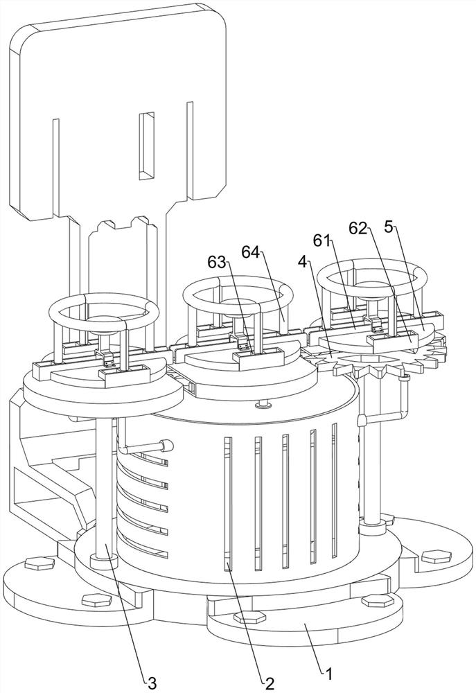
[0062] An optical lens ink coating device, such as Figure 1-4 As shown, it includes a mounting frame 1, a reduction motor 2, a vertical rod 3, a gear 4, a placement seat 5, a clamping assembly 6 and an ink application assembly 7. A reduction motor 2 is provided on the front side of the top of the mounting frame 1. Both left and right sides of the upper part are equipped with a vertical rod 3, and the upper part of the vertical rod 3 and the output shaft of the reduction motor 2 are provided with a gear 4, and the two adjacent gears 4 are meshed with each other, and the top of the vertical rod 3 is connected to the output shaft of the reduction motor 2. The output shaft is provided with a placement seat 5, and the placement seat 5 is provided with a clamping assembly 6 that can fix the lens, and the upper side of the mounting frame 1 rear is provided with an inking assembly 7 that applies ink to the lens.

[0063] When the optical lens needs to be coated with ink, the staff fi...

Embodiment 2

[0069] On the basis of Example 1, such as figure 1 , figure 2 , Figure 5 , Image 6 and Figure 7 As shown, a test assembly 8 is also included. The test assembly 8 includes an electric storage box 81, a measuring lamp 82, a fixed block 83 and a radiation plate 84. Three groups of measuring lamps 82 are arranged horizontally on the lower side of the box 81, and each group is composed of two measuring lamps 82 on the left and right. The top of the long guide rail 61 is provided with a fixed block 83, and the top of the fixed block 83 is provided with a radiation plate 84. The radiation plate 84 Sleeved on the placement seat 5 , the radiation plate 84 corresponds to each group of measuring lamps 82 .

[0070] When the lens is coated with ink, turn on the measurement lamp 82, and the power storage box 81 supplies power to the measurement lamp 82. After the lens is coated with ink, the light of the measurement lamp 82 passes through the lens and shines on the radiation plate ...


PUM


Abstract

The invention relates to an ink coating device, in particular to an optical lens ink coating device. The technical problem to be solved by the invention is to provide the optical lens ink coating device which is quicker and uniform in coating, and particularly the optical lens inking device which is uniform in coating and high in working efficiency when the optical lens is coated. The optical lens ink coating device comprises a mounting frame, vertical rods, gears and a placement seat; a gear motor is arranged on the front portion of the mounting frame; the two vertical rods are rotationally mounted on the left side and the right side of the front portion of the mounting frame respectively; the gears are installed on the upper portion of the vertical rod and an output shaft of the gear motor, every two adjacent gears mesh with each other; and the placement seat is mounted on the tops of the vertical rods and the output shaft of the gear motor. According to the optical lens ink coating device, a measuring lamp can irradiate and penetrate through the lens so that a worker can observe the light transmittance to judge the ink coating thickness, a scraping plate can scrape away much ink, the precision of the lens is improved, and an air purifier can convert peculiar smell generated during ink coating to reduce emission of the peculiar smell.

Description

technical field [0001] The invention relates to an inking device, in particular to an optical lens inking device. Background technique [0002] When smearing optical lenses manually, in order to ensure that the ink is evenly applied to the lens, the staff need to smear the lens repeatedly, so as to complete the smearing of the optical lens on the basis of ensuring uniform smearing. In order to improve work efficiency, it is necessary Apply accurately and evenly to optical lenses. [0003] At present, when people apply ink to optical lenses, they first place the optical lenses on the workbench, and then the staff take tools to apply. Manual application not only takes a lot of time, but also causes uneven application. Therefore, after the inking is completed, the lens needs to be inspected additionally, and the work process is more, and the work efficiency is lower. [0004] Therefore urgently need to research and develop a kind of faster and the device that applies ink even...

Claims


Application Information

Patent Timeline
IPC IPC(8): B05C1/02B05C11/02B05C11/10B05C13/02
CPCB05C1/02B05C11/1005B05C11/10B05C11/023B05C13/02Y02E60/10
Inventor 聂俊
Owner 上饶市桐宇光电科技有限公司
Learn More