
Grinding equipment

A grinding and equipment technology, applied in the direction of grinding/polishing equipment, grinding frame, grinding bed, etc., can solve frequent clamping and positioning operations, increase grinding error, affect grinding efficiency and reduce grinding efficiency. problems such as grinding quality, to achieve the effect of compact and firm grinding mechanism and avoid tilting

Pending Publication Date: 2022-01-14
福州天瑞线锯科技有限公司
View PDF9 Cites 0 Cited by
  • Summary
  • Abstract
  • Description
  • Claims
  • Application Information

AI Technical Summary

Problems solved by technology

In this way, the whole process requires three kinds of processing equipment with different functions, and silicon rods need to be frequently carried out manually between the equipment and clamping and positioning operations before processing.
Thus affecting the grinding efficiency and grinding quality
[0003] At the same time, because in the prior art, the clamping assembly and the grinding piece in the grinding mechanism are separated, the separate setting will further increase the error during grinding

Method used


Image

  • Grinding equipment
  • Grinding equipment
  • Grinding equipment

Examples


Embodiment Construction

[0040] In order to explain in detail the technical content, structural features, achieved goals and effects of the technical solution, the following will be described in detail in conjunction with specific embodiments and accompanying drawings.

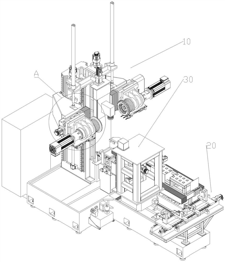
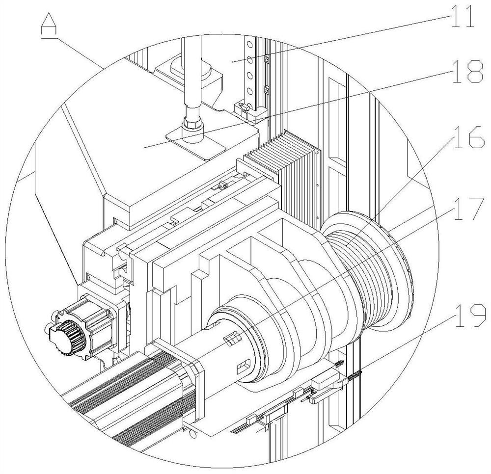
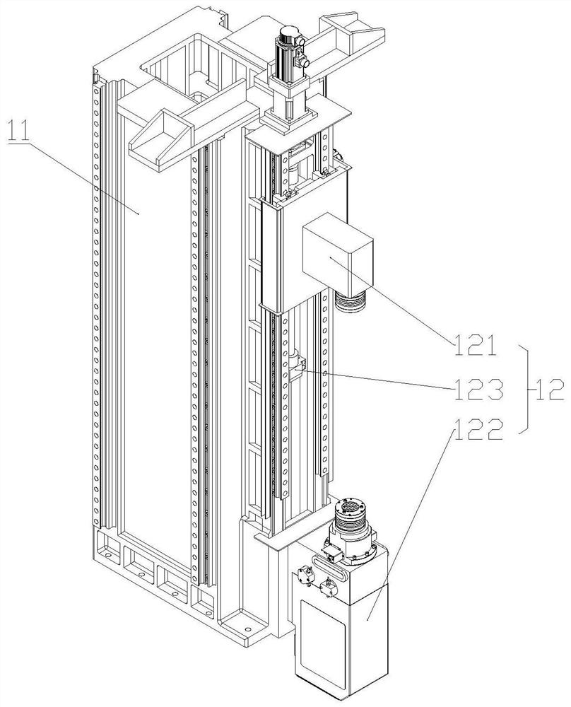
[0041] see Figure 1 to Figure 9 , the present application discloses a grinding device, including: a grinding mechanism 10; the grinding mechanism 10 includes: a column 11, a clamping assembly 12, a first grinding piece 13, a first bracket 14, a first power source 15. The clamping assembly 12 is slidably arranged on one side of the column 11, and the clamping assembly 12 moves in the vertical direction. The clamping assembly 12 is used to clamp the workpiece and drive the workpiece to rotate; the first One side of a support 14 is slidably connected with the column 11, and the other side of the first support 14 is slidably connected with the first grinding part 13; the first power source 15 is connected with the first grinding part 13 ...


PUM


Abstract

The invention discloses grinding equipment. A clamping assembly is arranged on one side of a stand column in a sliding mode, and the clamping assembly moves in the vertical direction; one side of a first support is slidably connected with the stand column, and the other side of the first support is slidably connected with a first grinding piece; a first power source is connected with the first grinding piece; the grinding end of the first grinding piece is arranged on one side of the movement track of the clamping assembly; the sliding track of the first support on the stand column is parallel to the sliding track of the clamping assembly on the stand column; the sliding track of the first grinding piece on the support is perpendicular to the sliding track of the first support on the stand column; and the first grinding piece moves in the direction close to or away from the movement track of the clamping assembly. The clamping assembly, the first grinding piece, the first support and the first power source are arranged on one same stand column, so that the grinding mechanism is more compact and firmer; and meanwhile, the movement track of the first support is always parallel to the movement track of the clamping assembly, so that the situation that the first support inclines in the vertical reciprocating motion process, and consequently the grinding precision is affected is avoided.

Description

technical field [0001] The invention relates to the technical field of rod-shaped workpiece processing, in particular to a grinding device. Background technique [0002] In the prior art, the machining processes of square cutting, edge grinding and surface grinding of silicon rods at home and abroad are usually three separate processes, which need to be transferred in three different equipment to complete the entire process. In actual operation, the single crystal silicon ingot is usually squared by a wire squarer, and then the squared silicon ingot is sent to the grinding mechanism for rounded corners and plane grinding. In this way, the whole process requires three kinds of processing equipment with different functions, and the silicon rods need to be frequently manually carried between the equipment and clamped and positioned before processing. Thus affecting the grinding efficiency and grinding quality. [0003] At the same time, because in the prior art, the clamping ...

Claims


Application Information

Patent Timeline
Patent Type & Authority Applications(China)
IPC IPC(8): B24B27/00B24B9/06B24B7/22B24B41/06B24B41/00B24B41/02B24B41/04
CPCB24B27/0076B24B9/06B24B7/222B24B41/06B24B41/005B24B41/02B24B41/04
Inventor 李海威陈扬贵韩开斌陈宗浩杨长友范舒彬李波赖晓锟
Owner 福州天瑞线锯科技有限公司
Learn More