Plastic product production material guiding system with thermal cycle constant temperature effect

A plastic product and heat cycle technology, applied in the field of plastic product production, can solve problems such as waste of resources, rapid emission of material direct discharge temperature, rise in surrounding environment temperature, etc., to avoid operating steps, convenient disassembly, cleaning and regular maintenance, and avoid environmental pollution. The effect of increasing temperature

Pending Publication Date: 2022-01-14
严仁苹
View PDF1 Cites 0 Cited by
  • Summary
  • Abstract
  • Description
  • Claims
  • Application Information

AI Technical Summary

Problems solved by technology

[0005] The purpose of the present invention is to provide a material guide system for the production of plastic products with thermal cycle constant temperature effect, to solve the problem that a large amount of heat will be condensed during the discharge process proposed in the above background technology, and its direct discharge will easily cause the temperature of the surrounding environment to rise. High waste of resources at the same time, and the direct discharge temperature of the discharged material is too fast, which is prone to rapid solidification, and whether waste heat collection and constant temperature can be combined is a problem worth considering

Method used


Image

  • Plastic product production material guiding system with thermal cycle constant temperature effect
  • Plastic product production material guiding system with thermal cycle constant temperature effect
  • Plastic product production material guiding system with thermal cycle constant temperature effect

Examples


Embodiment Construction

[0033] The following will clearly and completely describe the technical solutions in the embodiments of the present invention with reference to the accompanying drawings in the embodiments of the present invention. Obviously, the described embodiments are only some, not all, embodiments of the present invention. Based on the embodiments of the present invention, all other embodiments obtained by persons of ordinary skill in the art without making creative efforts belong to the protection scope of the present invention.

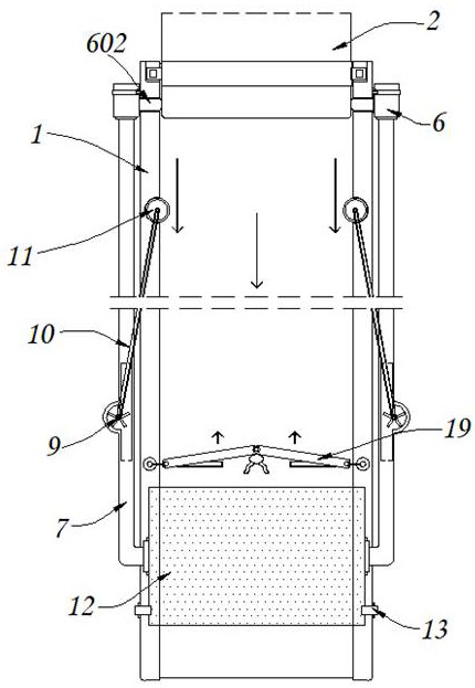
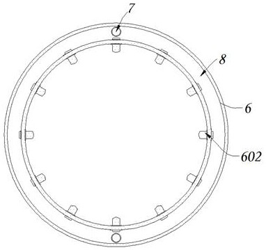
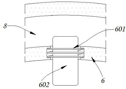
[0034] see Figure 1-7 , the present invention provides a technical solution: a material guide system for the production of plastic products with thermal cycle and constant temperature effects, including a docking part 1, a preset feeding part 2, a limiting part 3, an accommodating tank 4, and a dark tank 5 , nesting part 6, return spring 601, heat conducting part 602, butt pipe fitting 7, heat collecting chamber 8, reserved blade 9, conveyor belt 10, nesting ...


PUM


Abstract

The invention discloses a plastic product production material guiding system with a thermal cycle constant temperature effect. According to the plastic product production material guiding system with the thermal cycle constant temperature effect, a preset material supply part is in butt joint with an external material supply equipment end, and a butt joint part is in butt joint with the outer side of the preset material supply part in a nested manner, the plastic product production material guiding system comprises limiting parts and containing grooves, wherein the limiting parts are fixedly connected to the outer side of the preset material supply part; and the containing grooves are formed in the inner side of the upper end of the butt joint part, and the containing grooves and covered grooves are both matched with the limiting parts to be in butt joint with the preset material supply part. According to the plastic product production material guiding system with the thermal cycle constant temperature effect, a large amount of heat condensed in the material discharging process is stably matched with self-rotating reserved blades through a copper heat conduction part in contact with a device in an attached mode to form a hot air lower guide state and is transmitted to a copper built-in constant-temperature part to perform constant-temperature treatment on materials, the situation that the temperature around the device increases and resources are wasted is avoided, furthermore, the discharged materials are in contact with heat conduction waste heat, and the bad phenomenon that the discharged temperature is dissipated too fast and rapid solidification is extremely prone to appearing is avoided.

Description

technical field [0001] The invention relates to the technical field of plastic product production, in particular to a material guide system for plastic product production with thermal cycle constant temperature effect. Background technique [0002] Plastic products have become one of the most common objects on the market, and their production process has gradually matured. The material guide structure in the production process is one of the more important components, but the existing material guide structure for plastic product production is still There are certain deficiencies, such as: [0003] For example, the material guide structure of the liquid heat-conducting adhesive whose publication number is CN212196019U can quickly and effectively complete the removal of air from the material guide pipe body, and pour the glue into the material box from the packaging tube, which is conducive to saving resources and labor. Some plastic product production will condense a large am...

Claims


Application Information

Patent Timeline
Patent Type & Authority Applications(China)
IPC IPC(8): B29C31/04B29C35/16
CPCB29C31/04B29C35/16
Inventor 严仁苹
Owner 严仁苹
Why Eureka
Try Eureka