Anti-clamping cross-seam comb-tooth type bridge expansion device

A telescopic device, comb type technology, used in bridges, bridge construction, bridge parts and other directions, can solve the problems of easy dust accumulation, easy damage, stuck stone, etc. The effect of the stone

Pending Publication Date: 2022-01-14
湖北恋桥交通工程有限公司
View PDF0 Cites 3 Cited by
  • Summary
  • Abstract
  • Description
  • Claims
  • Application Information

AI Technical Summary

Problems solved by technology

At present, a large number of Maurer telescopic devices are used. Dust and stones are easy to accumulate in the joints, and the car jumps obviously. The waterproof rubber is easy to detach and leaks.
Due to the stretchability of the steel cover, in order to prevent the steel cover from arching, a sufficient expansion space will be left at one end of the steel cover, but it will also cause no gaps in the road surface, resulting in bicycle wheel or stone jams

Method used


Image

  • Anti-clamping cross-seam comb-tooth type bridge expansion device
  • Anti-clamping cross-seam comb-tooth type bridge expansion device
  • Anti-clamping cross-seam comb-tooth type bridge expansion device

Examples


Embodiment 1

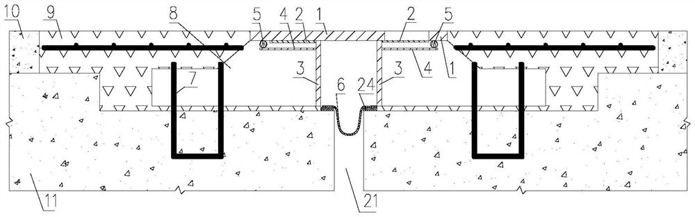
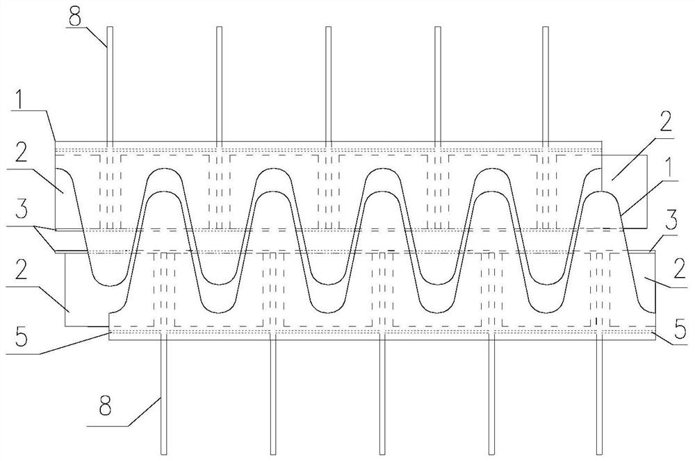
[0033] Embodiment one, such as figure 1 , 2 The small cantilever butt joint expansion device, the expansion of the beam gap is less than or equal to 240mm, and the structures on both sides of the beam gap are symmetrically arranged, such as figure 2 The comb teeth in the embodiment are curved plates protruding longitudinally, and the overall shape is relatively small. The comb teeth are horizontally arranged in the shape of a plate, and the comb teeth can also be in the shape of rectangular strips, and a pair of opposite comb teeth are arranged alternately. figure 1 The top of the anchor plate 8 in the embodiment is directly welded to the bottom surface of the comb-tooth member 1. In order to enhance the smoothness of the road surface as much as possible, the shutter 2 is welded close to the bottom of the comb-tooth member 1, and the front end of the shutter 2 is welded to the side beam 3. Both sides reach the anchor plate 8 at the longest, and the rear part covers the alveo...

Embodiment 2

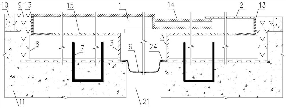
[0035] Embodiment two, such as image 3 , 4 Medium and large cantilever butt-joint expansion devices, the expansion of the beam gap is more than 320mm, and the structures on both sides of the beam gap are arranged symmetrically, which requires higher load-bearing and impact resistance performance. The thickness of the comb piece 1 is required to increase. In the embodiment, a special steel plate is used to cut a special shape, and a baffle plate 13 made of angle steel is used at the end to prevent cement from entering the gap on both sides of the comb piece. The comb tooth of the comb tooth piece 1 is a special shaped strip made of steel plate. In order to seal the hole in front of the tooth end, an extension tooth 14 is welded at the front end of the comb tooth piece 1, which has sufficient compression resistance and elasticity. Shield plate 2 is welded in the front slot of extension tooth 14, shield plate 2 is welded with the baffle plate 13 on the opposite side as a part o...

Embodiment 3

[0036] Embodiment three, such as Figure 5 , 6 The medium is a small joint-span supporting expansion device, the expansion of the beam joint is less than or equal to 240mm, and the structures on both sides of the beam joint are asymmetrically arranged. The comb piece is a horizontally arranged comb plate, the top of the anchor plate 8 on the opposite side is welded to the horizontal backing plate 15, the front end is welded to the side beam 3, and a baffle plate 13 is welded to the tail below the comb plate to prevent the rear Pour cement into it. A rubber support 17 is placed between the top of the anchor plate 8 and the comb plate 1 , and the post-cast concrete is flush with the top of the anchor plate 8 , and the rubber support 17 is laid on the concrete. A row of stepped stud holes is arranged horizontally behind the side beam 3 of the comb on one side. The stud holes are set on one side of the anchor plate 8. The studs 22 pass through the stud holes. The lower part is w...


PUM


Abstract

The invention discloses an anti-clamping cross-seam comb-tooth type bridge expansion device, and solves a problem that wheels and stones are clamped by deep and long potholes of a traditional large comb-tooth type bridge expansion device. The fixed tooth pit slot filling and lifting method comprises steps that the tooth length is increased in the post-cast strip direction of the telescopic device, pit slots with certain lengths of adjacent teeth are covered, inter-tooth cavities with certain lengths corresponding to the models are formed, inter-tooth bearing beams with the corresponding lengths are vertically and movably connected to the corresponding tooth ends, the bearing beams have enough strength, during use, the size of the top surface of the full-pit slot long inner bearing beam is only about 15mm lower than that of the tooth top. According to comb tooth beam seam bolt side pit slot filling and lifting, two steel plates are welded to the movable tooth side through the I-shaped cross section of a fixed tooth side tooth beam, and a 20-25 mm gap needed by stretching and retracting of a fixed tooth I-shaped beam web is reserved. After treatment, a top surface of a pit slot on the movable tooth side is about 20mm lower than the road surface, so the conditions of wheel clamping and stone clamping are avoided.

Description

technical field [0001] The invention relates to bridge construction, in particular to an anti-blocking wheel / stone-blocking comb-tooth type bridge telescopic device. Background technique [0002] The bridge girder joint is a bridge building to adapt to the shrinkage and expansion setting. When the bridge deck is paved, it is necessary to set up waterproof and adaptable scalable pavement at the expansion joint. Dimensional change in shrinkage and expansion in the transverse direction. The currently widely used Maurer telescopic devices tend to accumulate dust and stones in the joints, and the car jumps obviously. The waterproof rubber is easy to detach and leak water. Due to the flexibility of the steel cover, in order to prevent the steel cover from arching, a sufficient expansion gap will be left at one end of the steel cover, but this will also result in no gaps in the road surface, resulting in bicycle wheel or stone jamming. Contents of the invention [0003] The tec...

Claims


Application Information

Patent Timeline
Patent Type & Authority Applications(China)
IPC IPC(8): E01D19/06
CPCE01D19/06E01D19/062
Inventor 鲁小华姜浩贺丁周晓刚
Owner 湖北恋桥交通工程有限公司
Why Eureka
Try Eureka