
Hand-push type automatic road sweeper

A hand-push, sweeper technology, applied in road cleaning, cleaning methods, construction and other directions, can solve the problem of inability to enter the interior of the floor for cleaning, and achieve the effects of convenient dumping, convenient cleaning, and increased air

Pending Publication Date: 2022-01-14
CHINA CONSTR SECOND ENG BUREAU LTD
View PDF8 Cites 0 Cited by
  • Summary
  • Abstract
  • Description
  • Claims
  • Application Information

AI Technical Summary

Problems solved by technology

[0003] At present, for the ground cleaning of the construction site, the road sweeper is generally used to clean the construction road. For the cleaning of the construction site and the interior of the floor, the general road sweeper cannot enter the interior of the floor for cleaning due to its large size. , therefore, it is necessary to provide a hand-push automatic road sweeper to solve the above technical problems

Method used


Image

  • Hand-push type automatic road sweeper
  • Hand-push type automatic road sweeper
  • Hand-push type automatic road sweeper

Examples


Embodiment 1

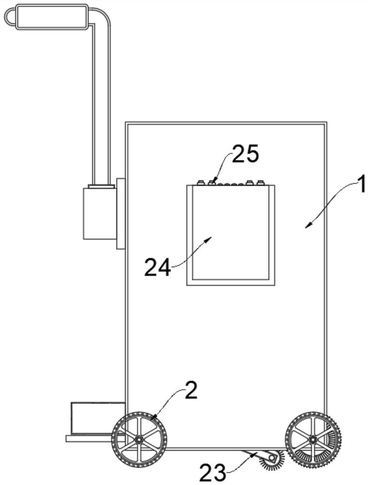
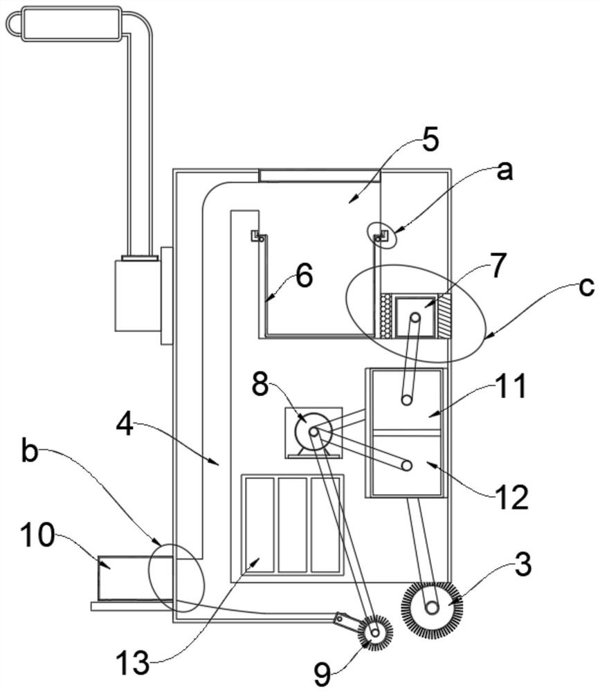
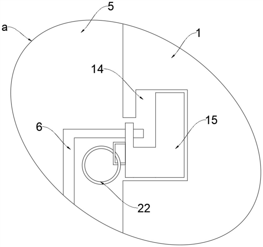
[0029] see Figure 1-6 , a hand-push automatic road sweeper, comprising a collection box 1, two sets of symmetrical moving wheels 2 are arranged on both sides of the bottom of the collection box 1, and the middle part of the moving wheels 2 on one side of the collection box 1 is rotatably connected with a cleaning Roller 3, the side of the collection box 1 away from the cleaning roller 3 is connected with a bulk collection box 10, the bulk collection box 10 communicates with the interior of the collection box 1, and the top of the collection box 1 is provided with a dust collection bin 5 and The outside of the bulk collection box 10 is connected, and the side of the bottom of the dust collection bin 5 is provided with a fan box 7, and the side of the fan box 7 away from the dust collection bin 5 is connected to the outside of the collection box 1. The collection box 1 The middle part is provided with a driving motor 8, and the transmission end of the driving motor 8 is connect...

Embodiment 2

[0032] This embodiment is an improvement made on Embodiment 1. For details, please refer to figure 2 , Figure 4 , the bottom surface of the collection box 1 is located inside the cleaning roller 3 and is provided with an inner rolling roller 9, the two ends of the inner rolling roller 9 are fitted with a diagonal strut 23, and the other end of the diagonal strut 23 is fixed on the inner side of the bottom surface of the collection box 1 , the inner winding roller 9 is in transmission connection with the drive motor 8 .

[0033] In this embodiment: the bottom surface of the collection box 1 is located at the inner winding roller 9 inside the cleaning roller 3, and the dust and stones swept into the bottom of the collection box 1 by the cleaning roller 3 can be swept into the inside of the collection box 1 in reverse, and transported to the collection box 1 and the inside of the bulk collection box 10, avoiding the accumulation of stones and dust in the middle of the collecti...

Embodiment 3

[0035] This embodiment is an improvement made on Embodiment 1. For details, please refer to figure 2 , between the drive motor 8 and the cleaning roller 3, a deceleration box 12 is provided, the drive end on one side of the deceleration box 12 is connected to the drive motor 8, and the transmission end on the other side of the deceleration box 12 is connected to the cleaning roller 3 drive connections.

[0036] In this embodiment: the deceleration box 12 that is provided with between the driving motor 8 and the cleaning roller 3 can reduce the rotating speed of the driving motor 8, so as to prevent the driving motor 8 from driving the cleaning roller 3 to rotate too fast, causing the cleaning roller 3 to spin. Damage, while effectively controlling the movement speed of the movement.


PUM


Abstract

The invention discloses a hand-push type automatic road sweeper which comprises a collecting box, two sets of symmetrical moving wheels are arranged on the two sides of the bottom of the collecting box, a sweeping roller is arranged in the middle of the moving wheels located on one side of the collecting box in a penetrating mode, a large block collecting box is connected to the side, away from the sweeping roller, of the collecting box, and the large block collecting box communicates with the interior of the collecting box. A dust collecting bin is formed in the top of the collecting box and communicated with the outer side of the large block collecting box, an air draft blade box is arranged on one side of the bottom of the dust collecting bin, the side, away from the dust collecting bin, of the air draft blade box is communicated with the outer side of the collecting box, a driving motor is arranged in the middle of the collecting box, and the driving end of the driving motor is in transmission connection with the air draft blade box and the sweeping roller. In the walking process of the moving wheels, the sweeping rollers can sweep garbage and dust on the ground at the bottom, stone and dust can be directly and automatically separated during cleaning, the dust adsorption function is achieved during dust cleaning, and the problem that the surrounding environment is polluted when the equipment moves is solved.

Description

technical field [0001] The invention relates to the field of road cleaning, in particular to a hand-push automatic road cleaning vehicle. Background technique [0002] Sweeper is a new type of high-efficiency cleaning equipment that integrates road cleaning, garbage recycling and transportation. It is a model equipment suitable for all-round cleaning of factories, highways, parks, squares and other roads. This new model can complete ground cleaning at one time. , road curb side cleaning, road curb cleaning and watering on the ground after cleaning, etc., suitable for cleaning operations in various climates and different dry road surfaces. [0003] At present, for the ground cleaning of the construction site, the road sweeper is generally used to clean the construction road. For the cleaning of the construction site and the interior of the floor, the general road sweeper cannot enter the interior of the floor for cleaning due to its large size. Therefore, it is necessary to ...

Claims


Application Information

Patent Timeline
Patent Type & Authority Applications(China)
IPC IPC(8): E01H1/08
CPCE01H1/0845
Inventor 李长江王永一郭赢姚望林陇蒋明伟李林峻夏凡孙涛刘兰波李和涛罗文询
Owner CHINA CONSTR SECOND ENG BUREAU LTD
Learn More