Antenna support maintenance platform based on shared tower and use method thereof
A technology for overhauling platforms and antenna brackets is applied in the directions of scaffolding supported by housing structures, housing structure supports, housing structure supports, etc., and can solve problems affecting the normal function of power towers, hidden dangers of safe operation of power lines, and maintenance of transmission cable obstructions. , to achieve the effect of improving safety and convenience, facilitating replacement and maintenance, and reducing the load
- Summary
- Abstract
- Description
- Claims
- Application Information
AI Technical Summary
Problems solved by technology
Method used
Image
Examples
Embodiment 1
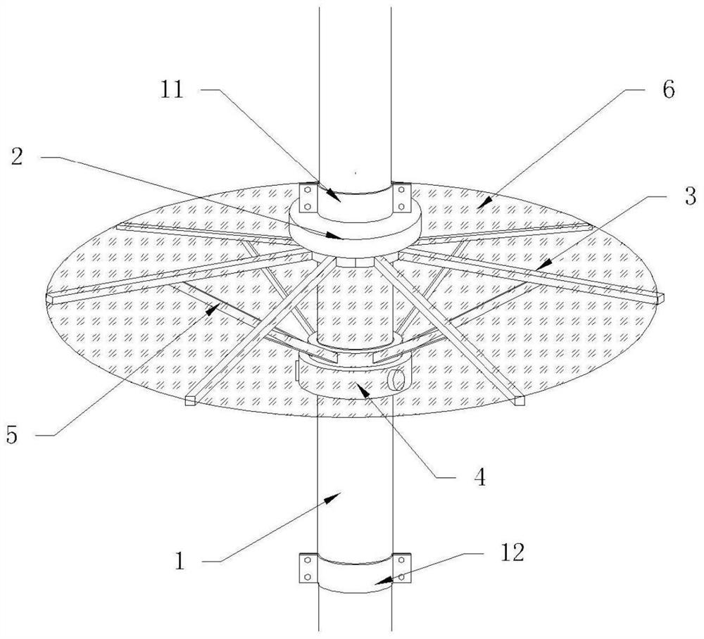
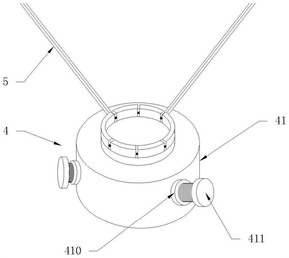
[0026] Such as Figure 1-3 As shown, an antenna support maintenance platform based on a shared pole tower is installed on the pole tower and is located below the communication equipment to facilitate the maintenance of communication personnel. The maintenance platform includes a sleeve 1, a fixed seat 2, a pole 3, a sliding sleeve 4, and a connecting rod 5 and supporting surface 6.
[0027] The inner diameter of the sleeve 1 matches the outer diameter of the tower, and is fixedly sleeved on the outside of the tower. The top and bottom ends of the sleeve 1 are welded to the upper hoop 11 and the lower hoop 12 respectively, and the upper hoop 11 and the lower hoop 12 are fixedly installed on the On the tower, the stability of the installation of the sleeve 1 is further improved.
[0028] The fixed seat 2 is a cylindrical structure matching the pole tower, fixedly installed on the top of the sleeve 1, located below the upper hoop 11, and several support rods 3 are evenly arrange...
Embodiment 2
[0034] A method for using an antenna support maintenance platform based on a shared tower, comprising the following steps:
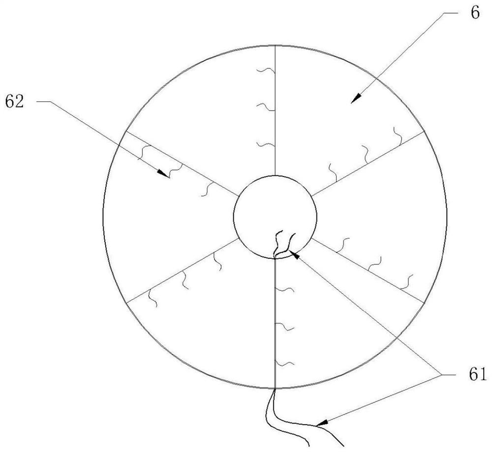
[0035] S1: Initially, the maintenance platform is in the retracted state, and the strap 61 on the longer arc side of the support surface 6 is bound to the sleeve 1. When in use, first untie the strap 61, and then move the sliding sleeve 4 upward to make the connecting rod 5 Drive the support rod 3 to prop up and open until the support rod 3 is in a horizontal state and the support surface 6 is opened;
[0036] S2: Turn the clamping bolt 411 inwardly against the sleeve 1 to fix the sliding sleeve 4. At this time, the support surface 6 can be used as an inspection platform;
[0037] S3: After use, screw the clamping bolt 411 outward, loosen the connection between the sliding sleeve 4 and the sleeve 1, move the sliding sleeve 4 downward, and drive the tail end of the support rod 3 to converge downward through the connecting rod 5 until the support Rod 3 is...
PUM
 Abstract
Description
Claims
Application Information
 - R&D
- Intellectual Property
- Life Sciences
- Materials
- Tech Scout
- Unparalleled Data Quality
- Higher Quality Content
- 60% Fewer Hallucinations
Browse by: Latest US Patents, China's latest patents, Technical Efficacy Thesaurus, Application Domain, Technology Topic, Popular Technical Reports.
© 2025 PatSnap. All rights reserved.Legal|Privacy policy|Modern Slavery Act Transparency Statement|Sitemap|About US| Contact US: help@patsnap.com


