
Measurement indicating device and method for relay pressure plate

A technology of measuring indication and pressing plate, applied in the direction of measuring device, measuring electric variable, measuring current/voltage, etc., can solve the problems such as affecting the safe operation of substations, wrong operation of outlet pressing plate, and wrong judgment.

Pending Publication Date: 2022-01-14
GUANGDONG POWER GRID CO LTD +1
View PDF0 Cites 2 Cited by
  • Summary
  • Abstract
  • Description
  • Claims
  • Application Information

AI Technical Summary

Problems solved by technology

[0003] At present, when substation operators measure the voltage at both ends of the outlet pressure plate, they use a high-resistance multimeter, and then judge whether the outlet pressure plate can be put in according to the voltage at both ends measured by the multimeter. Judging by relevant knowledge is very easy to cause wrong judgment due to memory deviation, which will lead to misplacement of the outlet pressure plate and affect the safe operation of the substation

Method used


Image

  • Measurement indicating device and method for relay pressure plate
  • Measurement indicating device and method for relay pressure plate
  • Measurement indicating device and method for relay pressure plate

Examples


Embodiment 1

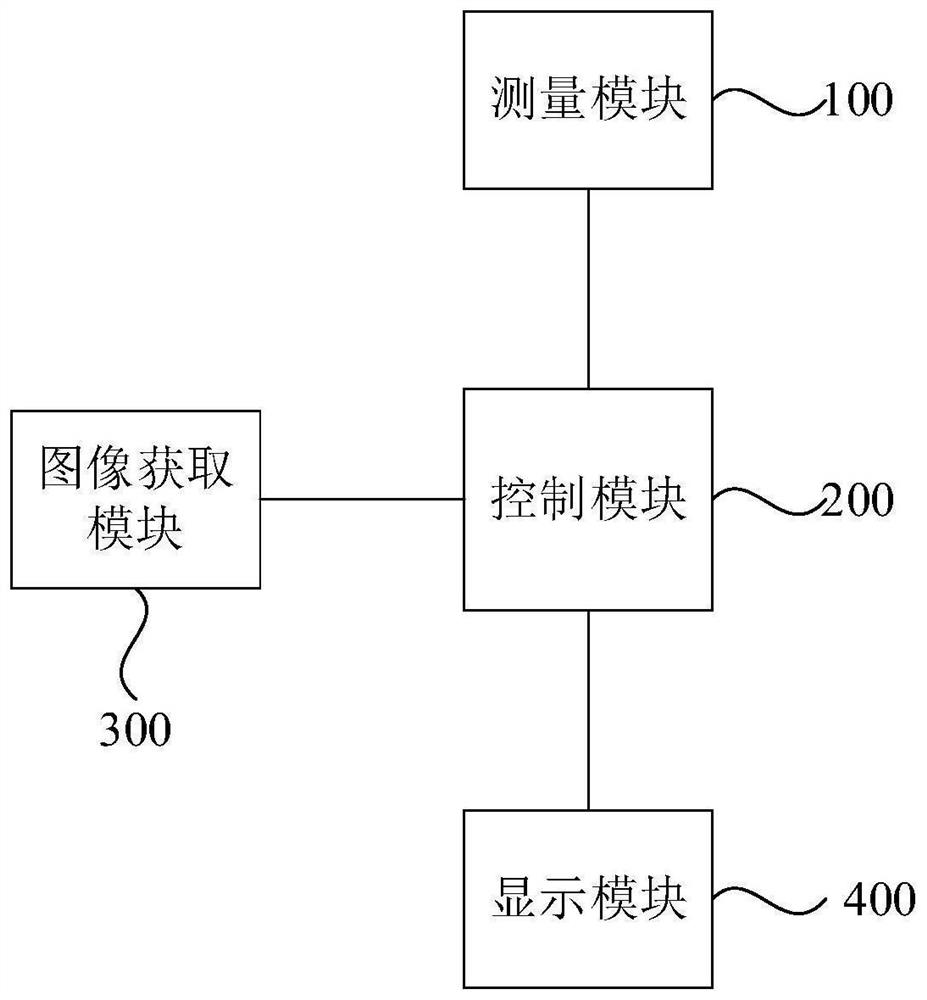
[0043] figure 1 A schematic structural diagram of a measuring and indicating device for a pressure-retaining plate provided in Embodiment 1 of the present invention, refer to figure 1 , the measurement indicating device for the pressure-holding plate includes a measurement module 100, a control module 200, an image acquisition module 300, and a display module 400;

[0044] The image acquisition module 300 is electrically connected to the control module 200, and the image acquisition module 200 is used to acquire the identification information of the relay pressure-holding plate to be tested, which includes the outlet pressure plate to be tested;

[0045] The measurement module 100 is electrically connected to the control module 200, and the measurement module 100 is used to respectively measure the voltage at the first end and the voltage at the second end of the outlet pressure plate to be tested;

[0046]The control module 200 is used to determine the input judgment result ...

Embodiment 2

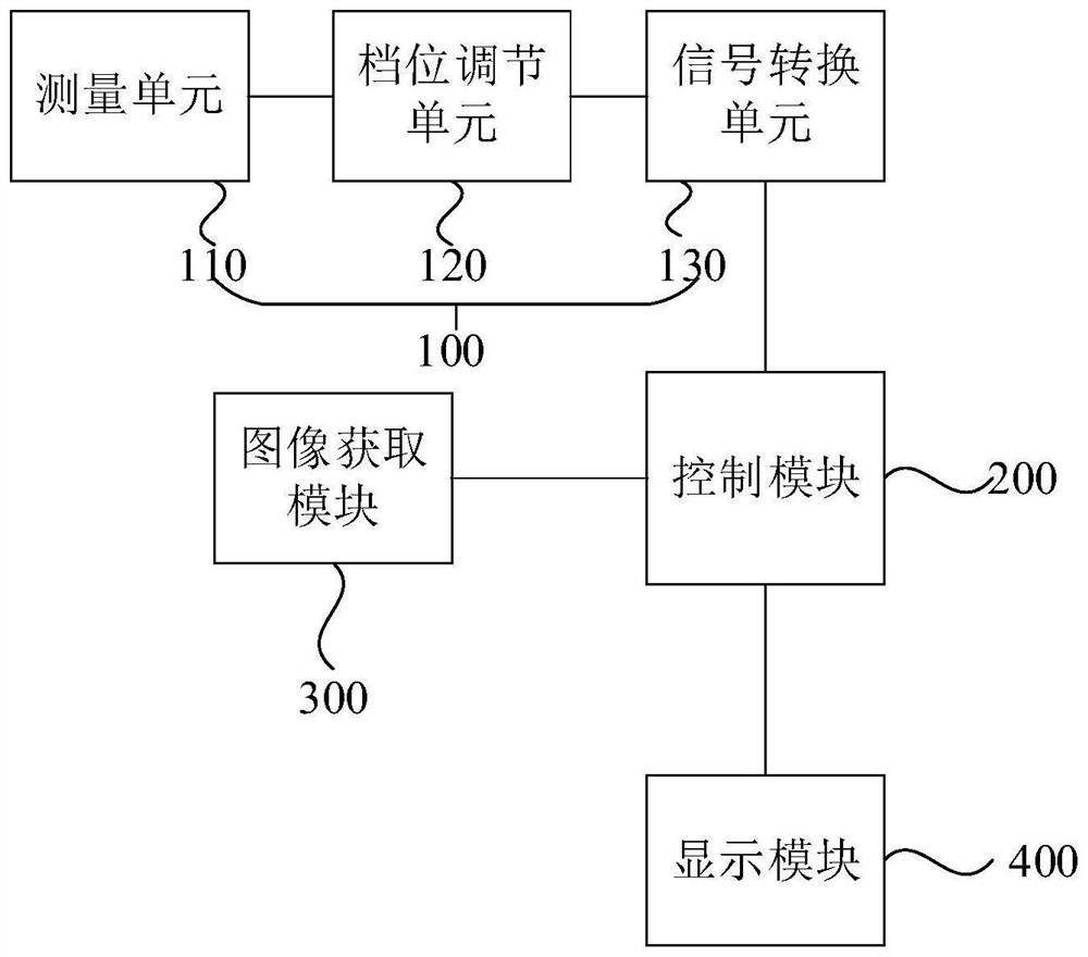
[0059] image 3 A schematic structural diagram of a measuring and indicating device for a pressure-retaining plate provided in Embodiment 2 of the present invention. On the basis of Embodiment 1 above, optionally, refer to image 3 , the measurement module 100 includes a measurement unit 110, a gear adjustment unit 120, and a signal conversion unit 130;

[0060] The measuring unit 110 is used to connect the test end of the outlet pressure plate to be tested and the ground wire, and the test end of the outlet pressure plate to be tested is the first end or the second end of the outlet pressure plate to be tested;

[0061] The gear adjusting unit 120 is electrically connected to the measuring unit 110, and the gear adjusting unit 120 is used to adjust the measuring gear of the measuring unit 110;

[0062] One end of the signal conversion unit 130 is electrically connected to the gear adjustment unit 120 , and the other end is electrically connected to the control module 200 . T...

Embodiment 3

[0068] Figure 4 A structural schematic diagram of a measuring and indicating device for a relay pressure-holding plate provided in Embodiment 3 of the present invention. On the basis of the above-mentioned embodiments, refer to Figure 4 , optionally, the control module 200 includes a processing unit 210 and a storage unit 220, and the processing unit 210 is electrically connected to the measurement module 100, the image acquisition module 300, the display module 400 and the storage unit 220, respectively;

[0069] The storage unit 220 is used for pre-storing the data information of a plurality of outlet pressure plates, and the data information of the multiple outlet pressure plates includes the data information of the outlet pressure plate to be tested.

[0070] The data information of each outlet pressure plate included in the power grid system can be pre-stored in the storage unit 220, so that when the measurement of the outlet pressure plate to be tested is performed and...


PUM


Abstract

The invention discloses a measurement indicating device and method for a relay pressure plate. The measurement indicating device for the relay pressure plate comprises a measurement module, a control module, an image acquisition module and a display module. The image acquisition module is electrically connected with the control module and is used for acquiring identification information of a to-be-tested relay pressure plate. The measuring module is electrically connected with the control module and is used for measuring the voltage of the first end and the voltage of the second end of a to-be-tested outlet pressure plate; and the control module is used for determining an input judgment result of the to-be-tested outlet pressure plate according to pre-stored data information of the to-be-tested outlet pressure plate, the voltage of the first end of the to-be-tested outlet pressure plate and the voltage of the second end of the to-be-tested outlet pressure plate. According to the measurement indicating method of the relay pressure plate provided by the embodiment of the invention, mistaken input of the to-be-detected outlet pressure plate caused by deviation of related knowledge memorized by an operator when the operator is used for judging whether the to-be-detected outlet pressure plate is switched on or not can be avoided, so that the input accuracy of the to-be-detected pressure plate is improved, and the safe operation of a transformer substation is ensured.

Description

technical field [0001] The embodiments of the present invention relate to the technical field of relay protection, and in particular to a measuring and indicating device and method for a relay maintaining pressure plate. Background technique [0002] The outlet pressure plate of the substation protection device is an important part of the protection circuit, mainly referring to the protection trip pressure plate, the start-up failure pressure plate, the failure joint trip pressure plate, etc. When the protection device has action contacts stuck or the action relay does not return, the substation operator If Putting the outlet pressure plate in without measurement will cause the circuit breaker to trip by mistake, causing unnecessary losses and affecting the safety and stability of the power grid. Therefore, when it comes to the operation of re-commissioning the outlet pressure plate, the substation operator needs to measure the voltage at both ends of the pressure plate befo...

Claims


Application Information

Patent Timeline
IPC IPC(8): G01R19/00G01R15/22
CPCG01R19/0084G01R15/22
Inventor 林鹏洲谢伟宏陈奕聪
Owner GUANGDONG POWER GRID CO LTD
Learn More