

Optical lens, camera module and electronic equipment
An optical lens and lens technology, applied in optics, optical components, instruments, etc., can solve problems such as insufficient image size, difficulty in effectively improving the pixels of electronic products, and difficulty in matching photosensitive elements on the photosensitive surface, so as to shorten and reduce spherical aberration Overall length, the effect of improving image quality
- Summary
- Abstract
- Description
- Claims
- Application Information
AI Technical Summary
Problems solved by technology
Method used
Image

Examples
Embodiment 1
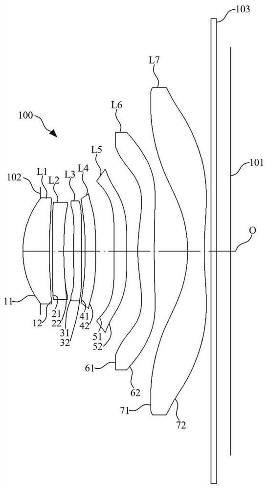
[0078] The structural schematic diagram of the optical lens 100 disclosed in Embodiment 1 of the present invention is as follows figure 1 As shown, the optical lens 100 includes a diaphragm 102, a first lens L1, a second lens L2, a third lens L3, a fourth lens L4, a fifth lens L5, a first lens L1, a fourth lens L4, a fifth lens L5, and a first lens L1 arranged sequentially from the object side to the image side along the optical axis O. Six lenses L6, a seventh lens L7 and a filter 103.
[0079] Further, the first lens L1 has a positive refractive power, the second lens L2 has a negative refractive power, the third lens L3 has a positive refractive power, the fourth lens L4 has a negative refractive power, and the fifth lens L5 has a negative refractive power , the sixth lens L6 has positive refractive power, and the seventh lens L7 has negative refractive power.
[0080] Further, the object side 11 and image side 12 of the first lens L1 are respectively convex and concave at...
Embodiment 2
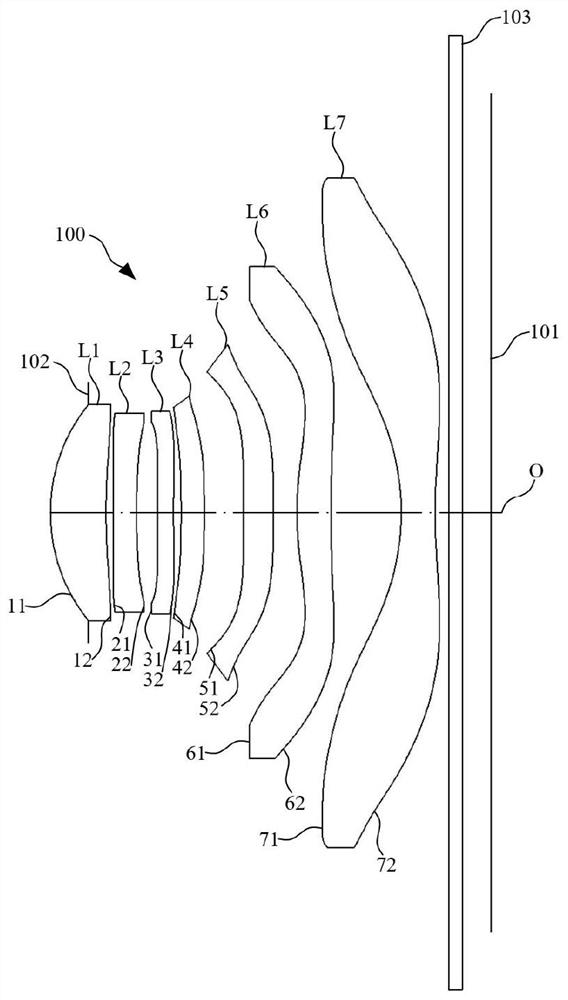
[0094] The structural schematic diagram of the optical lens 100 disclosed in Embodiment 2 of the present invention is as follows image 3 As shown, the optical lens 100 includes a diaphragm 102, a first lens L1, a second lens L2, a third lens L3, a fourth lens L4, a fifth lens L5, a first lens L1, a fourth lens L4, a fifth lens L5, and a first lens L1 arranged sequentially from the object side to the image side along the optical axis O. Six lenses L6, a seventh lens L7 and a filter 103.
[0095] Further, the first lens L1 has a positive refractive power, the second lens L2 has a negative refractive power, the third lens L3 has a positive refractive power, the fourth lens L4 has a positive refractive power, and the fifth lens L5 has a negative refractive power, Sixth lens L6 has positive refractive power, and seventh lens L7 has negative refractive power.
[0096] Further, the object side 11 and image side 12 of the first lens L1 are respectively convex and concave at the near...
Embodiment 3
[0106] The structural schematic diagram of the optical lens 100 disclosed in Embodiment 3 of the present invention is as follows Figure 5 As shown, the optical lens 100 includes a diaphragm 102, a first lens L1, a second lens L2, a third lens L3, a fourth lens L4, a fifth lens L5, a first lens L1, a fourth lens L4, a fifth lens L5, and a first lens L1 arranged sequentially from the object side to the image side along the optical axis O. Six lenses L6, a seventh lens L7 and a filter 103.
[0107] Further, the first lens L1 has a positive refractive power, the second lens L2 has a negative refractive power, the third lens L3 has a negative refractive power, the fourth lens L4 has a positive refractive power, and the fifth lens L5 has a negative refractive power , the sixth lens L6 has positive refractive power, and the seventh lens L7 has negative refractive power.
[0108] Further, the object side 11 and image side 12 of the first lens L1 are respectively convex and concave a...
PUM
 Abstract
Description
Claims
Application Information