Tracking method and device
A technology of preset models and scattering images, which is applied in radiation therapy, X-ray/γ-ray/particle irradiation therapy, image data processing, etc., can solve the problems of encroaching on the treatment space and high difficulty in engineering realization, so as to increase the treatment space and engineering Easy to achieve, accurate position offset effect
- Summary
- Abstract
- Description
- Claims
- Application Information
AI Technical Summary
Problems solved by technology
Method used
Image

Examples
Embodiment 1
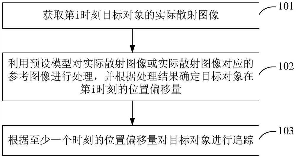
[0025] Embodiment 1 of the present application provides a tracking method, such as figure 1 as shown, figure 1 It is a flow chart of a tracking method provided in Embodiment 1 of this application. The tracking method includes the following steps:
[0026] Step 101. Acquire the actual scattering image of the target object at the i-th moment.
[0027] Wherein, i is an integer greater than 0, and the actual scattering image is generated according to the rays scattered by the body tissue where the target object is located.
[0028] Optionally, the actual scattering image is generated according to rays (for example, X-rays) irradiated to the body tissue (or object) where the target object is located, and the scattered rays are generated.
[0029] The target object may be an object to be tracked. For example, during radiotherapy, the target object may be a tumor to be tracked, and the body tissue where the target object is located may be the body tissue where the patient's tumor ...
Embodiment 2
[0052] Based on the tracking method described in the first embodiment above, the second embodiment of the present application combines the description of steps 101-103 in the first embodiment, taking the target object as a tumor as an example, and implements the tracking method provided by the embodiment of the present application in the tumor treatment scene Detailed description.
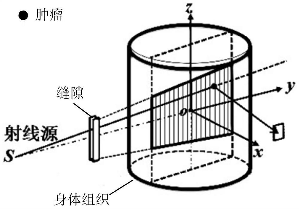
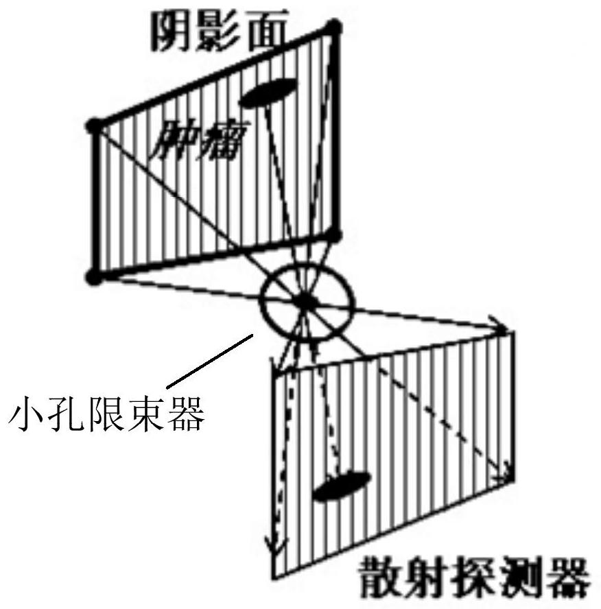
[0053] Such as Figure 2A as shown, Figure 2A It is a schematic diagram of a tumor treatment scene provided in Embodiment 2 of the present application. The radiation source S can emit X-rays. object), because X-rays have penetrating power, therefore, after the rays irradiate body tissues along the y-axis direction, the energy of X-rays gradually attenuates, and because different parts of different body tissues have different absorption capabilities for X-rays, so , the scattered X-rays can represent different parts of body tissue because of their different energies.
[0054] In the first applic...
Embodiment 3
[0065] Based on the tracking methods described in Embodiment 1 and Embodiment 2 above, Embodiment 3 of the present application provides a tracking device for implementing the tracking methods described in Embodiment 1 and Embodiment 2 above. Refer to image 3 As shown, the tracking device 30 includes: an acquisition module 301, an offset module 302 and a tracking module 303;
[0066] Wherein, the obtaining module 301 is used to obtain the actual scattering image of the target object at the i-th moment, i is an integer greater than 0, and the actual scattering image is generated according to the rays scattered by the body tissue where the target object is located;
[0067] The offset module 302 is configured to use a preset model to process the actual scatter image or the reference image corresponding to the actual scatter image, and determine the position offset of the target object at the i-th time according to the processing result, and the preset model is used to indicate th...
PUM
 Abstract
Description
Claims
Application Information
 - R&D
- Intellectual Property
- Life Sciences
- Materials
- Tech Scout
- Unparalleled Data Quality
- Higher Quality Content
- 60% Fewer Hallucinations
Browse by: Latest US Patents, China's latest patents, Technical Efficacy Thesaurus, Application Domain, Technology Topic, Popular Technical Reports.
© 2025 PatSnap. All rights reserved.Legal|Privacy policy|Modern Slavery Act Transparency Statement|Sitemap|About US| Contact US: help@patsnap.com