Forming die for manufacturing computer shell

A technology of forming molds and computers, which can be applied to household appliances, other household appliances, applications, etc., can solve problems such as low molding quality, faults, and reduced work efficiency, so as to reduce air content, speed up injection efficiency, and avoid imaging defects. Effect

Pending Publication Date: 2022-01-18
李楠
View PDF0 Cites 0 Cited by
  • Summary
  • Abstract
  • Description
  • Claims
  • Application Information

AI Technical Summary

Problems solved by technology

[0006] Aiming at the deficiencies of the prior art, the present invention provides a molding die for computer housing manufacturing, which solves the problem that the traditional computer housing molding die cannot evenly distribute the material and easily cause molding defects and material faults. The quality is low, and the shell cannot be actively removed after cooling and forming, which is inconvenient for workers to operate and reduces work efficiency.

Method used


Image

  • Forming die for manufacturing computer shell
  • Forming die for manufacturing computer shell
  • Forming die for manufacturing computer shell

Examples


Embodiment 1

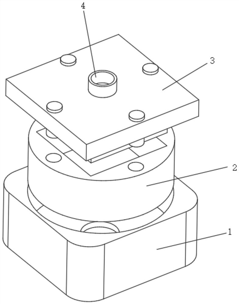
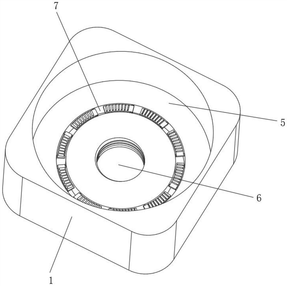
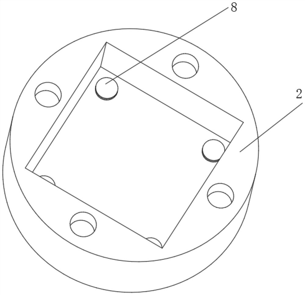
[0036] Such as Figure 1-4 As shown, the present invention provides a technical solution: a molding die for computer casing manufacturing, including a molding bottom frame 1, a concave template 2 is arranged above the molding bottom frame 1, and a molding convex mold is arranged above the concave template 2. The mold 3 is provided with a sprue mechanism 4 at the middle position of the top of the forming punch 3, and the middle position of the forming bottom frame 1 is provided with a restriction installation groove 5, and the middle position inside the restriction installation groove 5 is provided with a restriction spiral groove 6, and the restriction installation groove 5 and is located on the outside of the limiting helical groove 6, a shaker assembly 7 is arranged, and a top material assembly 8 is evenly arranged around the inside of the concave formwork 2, and the middle position of the outer bottom of the concave formwork 2 is fixedly connected with a drive screw rod 9, a...

Embodiment 2

[0038] Such as Figure 5-6 As shown, on the basis of Embodiment 1, the present invention provides a technical solution: a molding die used in the manufacture of computer casings. Inside, the position near the top of the rotating track 71 is rotatably connected with a movable pendulum plate 72 , and the surface of the top of the movable pendulum plate 72 is fixedly connected with a shaking protrusion 73 . Avoid the outward separation of the mold when it rotates, and ensure the relative stability of the mold rotation.

[0039]The inside of the rotating track 71 slides correspondingly with the movable slider 10 , and the shaking protrusion 73 slides in contact with the surface of the mating component 11 .

[0040] The mating component 11 includes an elastic connecting rod 111 , the back end of the elastic connecting rod 111 is fixedly connected with the movable slider 10 , and the outer end of the elastic connecting rod 111 is fixedly connected with a shaker contact plate 112 . ...

Embodiment 3

[0043] Such as Figure 7-8 As shown, on the basis of Embodiment 1 and Embodiment 2, the present invention provides a technical solution: a molding die for the manufacture of computer casings, the ejector assembly 8 includes a storage pad groove 81, and the storage pad groove 81 is set Inside the concave formwork 2, a stabilizing rod 82 runs through and is slidably connected to the middle of the storage cushion groove 81, and the top of the stable plunger 82 is fixedly connected with a material-removing backing plate 83, and the material-removing backing plate 83 is connected to the top of the storage cushion groove 81. Sealed fit set.

[0044] A sealed air bag 84 is fixedly connected to the bottom of the stabilizing rod 82 , movable inner grooves 85 are arranged on both sides near the top of the stabilizing rod 82 , and a heat conduction block 86 is fixedly connected to the inside of the movable inner groove 85 . Ensure the stability of the mold during molding and avoid the i...


PUM


Abstract

The invention discloses a forming die for manufacturing a computer shell, and relates to the technical field of computer manufacturing. The forming die comprises a forming bottom frame, a concave die plate is arranged above the forming bottom frame, a forming convex die is arranged above the concave die plate, a sprue mechanism is arranged in the middle of the top of the forming convex die, a limiting mounting groove is formed in the middle of the forming bottom frame, a limiting spiral groove is formed in the middle of the interior of the limiting mounting groove, a material shaking assembly is arranged in the position, located on the outer side of the limiting spiral groove, of the interior of the limiting mounting groove, material ejecting assemblies are evenly arranged on the periphery of the interior of the concave die plate, a movable sliding block is fixedly connected to the position, located on the outer side of a driving spiral rod, of the bottom end of the exterior of the concave die plate, and matching assemblies are evenly and fixedly connected to the surface of the outer surface area of the movable sliding block. According to the forming die for manufacturing the computer shell, the fluidity of materials inside a die cavity is improved, the imaging defect phenomenon is avoided, and the material injection efficiency is improved.

Description

technical field [0001] The invention relates to the technical field of computer manufacturing, in particular to a molding die for computer casing manufacturing. Background technique [0002] Computer manufacturing Industry that produces various computer systems, peripheral equipment, terminal equipment and other related devices. Together with the computer service industry, it constitutes the computer industry. [0003] The computer manufacturing industry is a knowledge- and technology-intensive industry that saves energy and resources and has high added value. It can bring huge economic and social benefits to the national economy and all aspects of society. Its scale and level have become an important indicator of a country's economic and military strength. [0004] The traditional computer case forming mold cannot distribute the material evenly, which is easy to cause forming defects and material faults, the forming quality is low, and the case cannot be actively removed...

Claims


Application Information

Patent Timeline
Patent Type & Authority Applications(China)
IPC IPC(8): B29C45/56B29C45/40B29L31/34
CPCB29C45/5605B29C45/568B29C45/4005B29C2045/5685B29L2031/3406
Inventor 李楠
Owner 李楠
Why Eureka
Try Eureka