Diffracted wave separation method and device
A diffracted wave and reflected wave technology, applied in the field of diffracted wave separation method and device, can solve the problems of large error, difficult to popularize and apply, and achieve the effect of enhancing robustness and adaptability and reducing accident risk.
- Summary
- Abstract
- Description
- Claims
- Application Information
AI Technical Summary
Problems solved by technology
Method used
Image

Examples
Embodiment 1
[0032] In order to facilitate the understanding of this embodiment, a method for separating diffracted waves disclosed in this embodiment of the present invention is firstly introduced in detail.
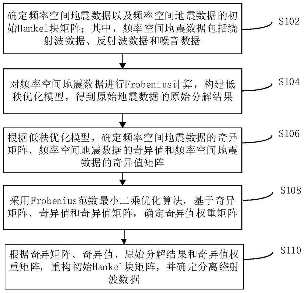
[0033] see figure 1 Shown is a flow chart of a method for separating diffracted waves, which method includes the following steps:
[0034] Step S102, determining the frequency space seismic data and the initial Hankel block matrix of the frequency space seismic data; wherein the frequency space seismic data includes diffracted wave data, reflected wave data and noise data.
[0035] Step S104, perform Frobenius calculation on the frequency-space seismic data, construct a low-rank optimization model, and obtain the original decomposition result of the original seismic data.
[0036] Step S106, according to the low-rank optimization model, determine the singular matrix of the frequency-space seismic data, the singular values of the frequency-space seismic data, and the singular valu...
Embodiment 2
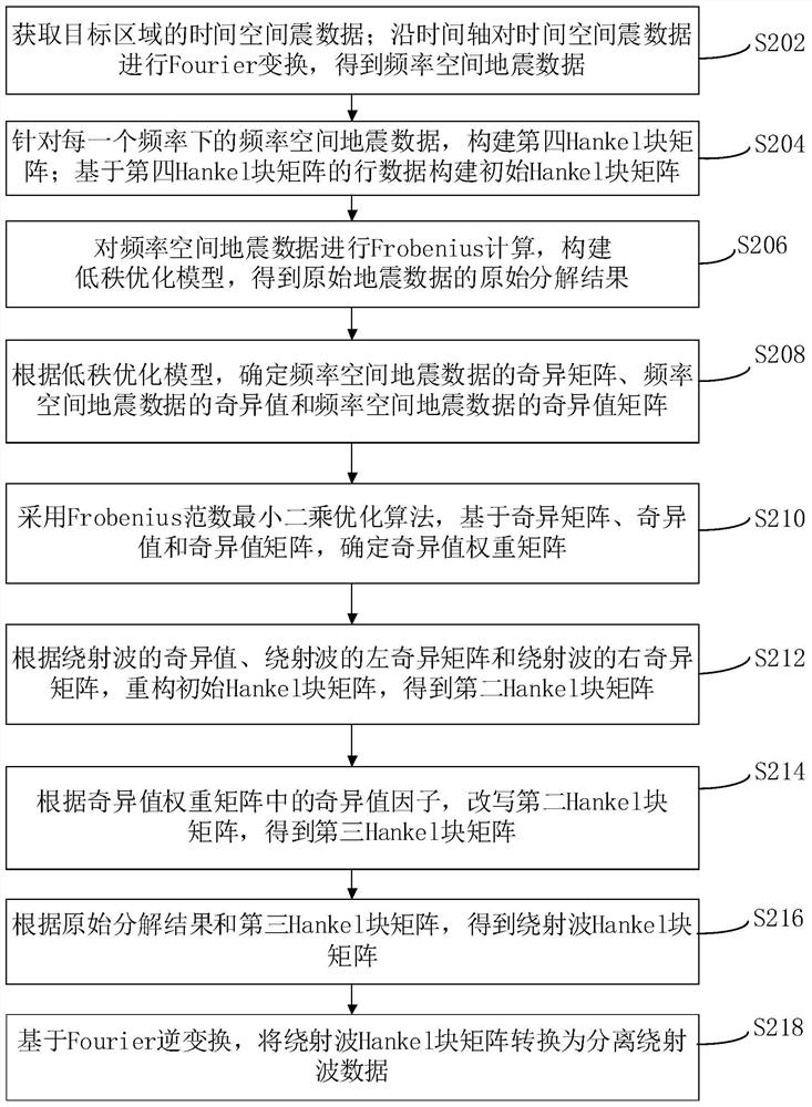
[0041] Another method for separating diffracted waves will be introduced in detail below. see figure 2 Shown is the flow chart of another kind of diffraction wave separation method, and this method comprises the following steps:
[0042] Step S202, acquiring time-space seismic data of the target area; performing Fourier transformation on the time-space seismic data along the time axis to obtain frequency-space seismic data.
[0043] Specifically, the time-space seismic data is also called seismic wavefield co-offset data, and the frequency-space seismic data is also called frequency-space domain seismic co-offset data. This operation can convert the original data from the time-space domain to the frequency-space domain, and the frequency-space domain is more convenient to process and the processing effect is better.
[0044] Step S204, constructing a fourth Hankel block matrix for the frequency-space seismic data at each frequency; constructing an initial Hankel block matri...
Embodiment 3
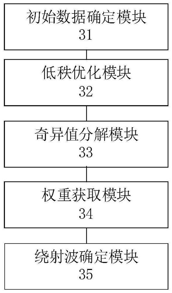
[0092] An embodiment of the present invention provides a device for separating diffracted waves, such as image 3 Shown, above-mentioned separating device comprises:
[0093] The initial data determination module 31 is used to determine the frequency space seismic data and the initial Hankel block matrix of the frequency space seismic data; wherein the frequency space seismic data includes diffracted wave data, reflected wave data and noise data.
[0094] The low-rank optimization module 32 is used to perform Frobenius calculation on the frequency-space seismic data, construct a low-rank optimization model, and obtain the original decomposition results of the original seismic data.
[0095] The singular value decomposition module 33 is configured to determine the singular matrix of the frequency-space seismic data, the singular values of the frequency-space seismic data, and the singular value matrix of the frequency-space seismic data according to the low-rank optimization ...
PUM
 Abstract
Description
Claims
Application Information
 - R&D Engineer
- R&D Manager
- IP Professional
- Industry Leading Data Capabilities
- Powerful AI technology
- Patent DNA Extraction
Browse by: Latest US Patents, China's latest patents, Technical Efficacy Thesaurus, Application Domain, Technology Topic.
© 2024 PatSnap. All rights reserved.Legal|Privacy policy|Modern Slavery Act Transparency Statement|Sitemap