
Tail shaft positioning device and accurate tail shaft positioning method

A technology of positioning device and tail shaft, which is applied in the direction of workpiece clamping device, manufacturing tools, etc., can solve the problems of large reading measurement error of drawing ruler, insufficient positioning accuracy of tail shaft, unfavorable maintenance of tail shaft positioning, etc., and achieves convenient operation and convenience The effect of tail shaft positioning inspection and convenient follow-up maintenance

Pending Publication Date: 2022-01-21
GUANGZHOU WENCHONG SHIPYARD CO LTD
View PDF5 Cites 0 Cited by
  • Summary
  • Abstract
  • Description
  • Claims
  • Application Information

AI Technical Summary

Problems solved by technology

[0003] This traditional positioning method uses a ruler to record data. Due to the error in the size of the ruler and the long measurement length, the measurement error of the reading using the ruler is large, the positioning accuracy of the tail shaft is not enough, and there are many devices around the tail shaft of some ship types. It is inconvenient to measure, and it is not conducive to the positioning of the tail shaft for subsequent maintenance
At the same time, two people are required to cooperate in the measurement of the ruler, which is affected by the operation mode of the measurement personnel, and the measurement error is relatively large

Method used


Image

  • Tail shaft positioning device and accurate tail shaft positioning method
  • Tail shaft positioning device and accurate tail shaft positioning method
  • Tail shaft positioning device and accurate tail shaft positioning method

Examples


Embodiment Construction

[0027] The present disclosure will be further described in detail below with reference to the drawings and embodiments. It can be understood that the specific implementation manners described here are only used to explain relevant content, rather than to limit the present disclosure. It should also be noted that, for ease of description, only parts related to the present disclosure are shown in the drawings.

[0028] It should be noted that, in the case of no conflict, the implementation modes and the features in the implementation modes in the present disclosure can be combined with each other. The present disclosure will be described in detail below with reference to the drawings and embodiments.

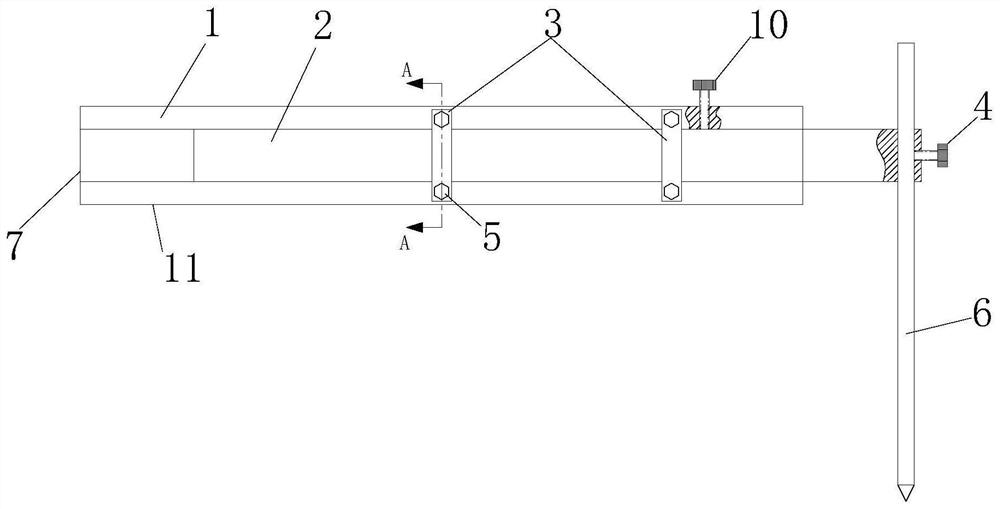
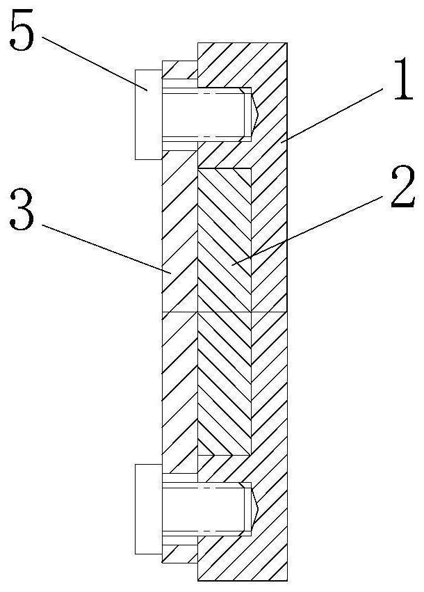
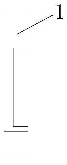
[0029] According to the first embodiment of the present disclosure, as Figure 1 to Figure 5 , provides a tail shaft positioning device, including an outer caliper 1, an inner caliper 2 and a positioning pin 6 arranged at one end of the inner caliper 2, the outer caliper 1 has a...


PUM


Abstract

The invention provides a tail shaft positioning device and an accurate tail shaft positioning method. The tail shaft positioning device comprises an outer caliper, an inner caliper and a positioning pin arranged at one end of the inner caliper. The outer caliper is provided with a sliding groove in the length direction, the inner caliper is slidably embedded in the sliding groove, and the outer caliper is provided with a first positioning face and a second positioning face. The first positioning face and the second positioning face are used for being tightly attached to a front shaft seal of a tail shaft. One end of the positioning pin is slidably arranged on the inner caliper, and the other end of the positioning pin is used for marking on the tail shaft. The outer caliper and the inner caliper are further provided with scales. Accurate positioning of the tail shaft is achieved through a special tool after the tail shaft is undocked. The rail shaft positioning device can be used as a ship-mounted spare part tool, which facilitates follow-up maintenance and use and is used for positioning and installing of the tail shaft after various ships are undocked. The positioning accuracy is improved after the tail shaft is undocked, and the situation is prevented that the reliability of installation data of a rear shaft seal and a protective cover of the tail shaft is affected by position changes of the tail shaft. The installation accuracy and the universality of an installation method are improved.

Description

technical field [0001] The disclosure relates to the field of prefabricated buildings, in particular to a tail shaft positioning device and a tail shaft precise positioning method. Background technique [0002] After the ship is undocked, the tail shaft needs to be positioned back to the state before it was undocked to ensure the reliability of the rear shaft seal of the tail shaft, the installation data of the protective cover and the fishing net knife. The traditional positioning method is to measure and record the distance from the end face of the stern shaft flange to the end face of the stern tube front gland with a ruler before undocking, measure again after undocking and position the stern shaft back to its original position. [0003] This traditional positioning method uses a ruler to record data. Due to the error in the size of the ruler and the long measurement length, the measurement error of the reading using the ruler is large, the positioning accuracy of the ta...

Claims


Application Information

Patent Timeline
IPC IPC(8): B25B11/00
CPCB25B11/00
Inventor 李荣昌陈锋何文明何卫何健许立干
Owner GUANGZHOU WENCHONG SHIPYARD CO LTD
Learn More