A diaphragm quality detection device and method thereof

A detection device and detection method technology, applied in the direction of measuring devices, optical devices, instruments, etc., can solve the problems of low detection efficiency of diaphragm thickness detectors, low efficiency of diaphragm quality detection, and inaccurate detection results, etc., and achieve reduction Difficulty in data processing, fast measurement speed, strong representative effect

Active Publication Date: 2022-04-19
湖南捷力泰科技有限公司
View PDF14 Cites 0 Cited by
  • Summary
  • Abstract
  • Description
  • Claims
  • Application Information

AI Technical Summary

Problems solved by technology

[0003] Diaphragm thickness detection instruments generally use a rangefinder for distance measurement, that is, through the reflection time of signals such as infrared rays to measure the distance before and after placing the diaphragm and make a difference to obtain the thickness of the diaphragm, and then according to the thickness of the diaphragm and the required The standard value of the diaphragm thickness judges whether the quality of the diaphragm is qualified. This measurement method only measures the center position of the diaphragm, and the data measurement accuracy is not high.
[0004] In view of the related technologies mentioned above, the inventor believes that if there are many sampling points, the detection efficiency of the diaphragm thickness detector will be low, which will lead to low detection efficiency of the diaphragm quality, too few sampling points, and inaccurate detection results. This needs to be further improved. Improve

Method used


Image

  • A diaphragm quality detection device and method thereof
  • A diaphragm quality detection device and method thereof
  • A diaphragm quality detection device and method thereof

Examples


Embodiment 1

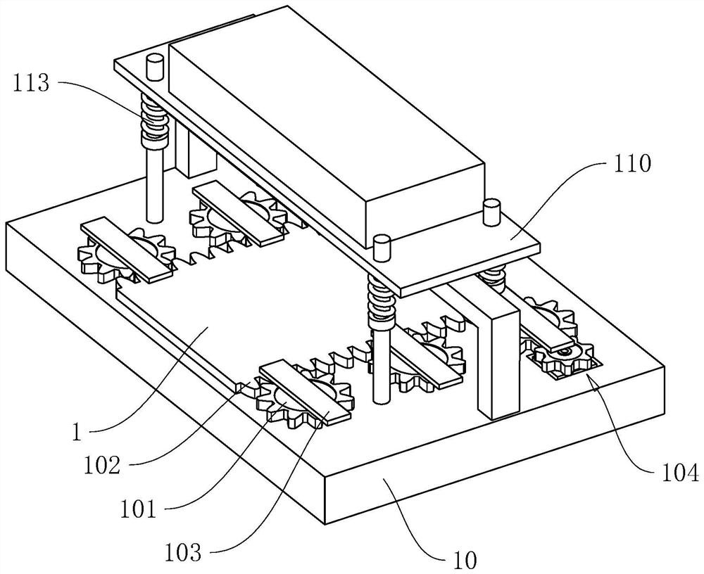
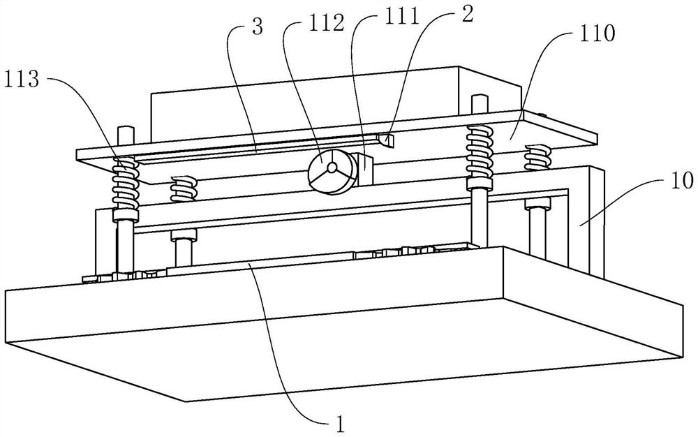
[0054] refer to figure 1 with figure 2 The diaphragm quality detection device includes a frame 10 on which a working plate 1 is slidably installed, and a thickness gauge is installed on the top of the frame 10, and the thickness gauge can measure the thickness of an object placed on the working plate 1. The thickness gauge includes a light emitting device 2, a light sensing device 3 and a data processing system.

[0055] The light emitting device 2 is arranged on one side of the frame 10. The emitting end of the light emitting device 2 faces the working board 1, and can emit a plurality of light beams that are on the same plane and have different angles from the upper surface of the working board 1 against the working board 1. Light, the light sensing device 3 and the light emitting device 2 are arranged side by side along the sliding direction perpendicular to the working plate 1 .

[0056] The emitting end of the light emitting device 2 and the receiving end of the light ...

Embodiment 2

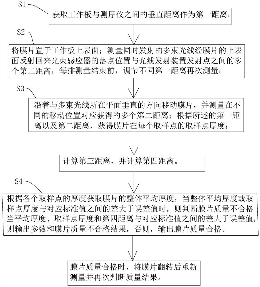
[0088] The difference between this embodiment and Embodiment 1 is that in order to improve the measurement accuracy, step S2 also includes: after the measurement of each row of sampling points is completed, the first distance L is adjusted by changing the overall height of the thickness gauge. In this embodiment, the first distance L is adjusted by adjusting the height of the thickness gauge twice, so that after the measurement of each row of sampling points is completed, three sets of sampling points for each row of sampling points are calculated by changing the first distance L twice. Point thickness X, and then calculate the average sampling point thickness of each row of sampling points through the average

[0089] Then the overall average thickness X of the diaphragm:

[0090]

[0091] in,

[0092] By setting multiple sets of data of the first distance L, measurement errors can be reduced, the accuracy of diaphragm thickness data measurement can be improved, and the...

Embodiment 3

[0094] The difference between this embodiment and other embodiments is that it also includes the following steps:

[0095] After step S3 is completed, the data processing system calculates the light corresponding to each sampling point in the light sensing device 3 according to the overall average thickness X, the acute angle θ formed by the corresponding light and the vertical line, and the first distance L through mathematical geometric relations. The third distance P between the theoretical landing point on the above and the emission point of the light emitting device 2; according to the third distance P and each sampling point corresponding to the second distance N, the fourth distance G is calculated through the difference, specifically through the following formula calculate:

[0096]

[0097] Among them, P i-k =2(L i-k -X)tanθ;

[0098] if there is G 3 If it is greater than the preset value, it is judged that the quality of the diaphragm is unqualified.

[0099]...


PUM


Abstract

The present application relates to a diaphragm quality detection device, which includes a frame, a working plate installed on the frame, and a thickness gauge installed on the frame for measuring the thickness of an object placed on the working plate. The instrument includes light emitting device, light sensing device and data processing system for processing information and displaying results. of light. The present application has the characteristics of improving the efficiency and precision of measuring the quality of the diaphragm when detecting the quality of the diaphragm, thereby improving the efficiency of judging whether the quality of the diaphragm is qualified or not.

Description

technical field [0001] The present application relates to the technical field of quality testing equipment, in particular to a diaphragm quality testing device and a method thereof. Background technique [0002] A diaphragm used in sounding devices such as speakers. Its quality, especially its thickness, affects the use of the speaker. Therefore, when producing the diaphragm, it is necessary to perform quality inspection on the diaphragm. Generally, by judging the diaphragm Whether the thickness of the diaphragm meets the standard is used to determine whether the quality of the diaphragm is qualified. Therefore, the diaphragm thickness inspection is an important part of the diaphragm quality inspection. [0003] Diaphragm thickness detection instruments generally use a rangefinder for distance measurement, that is, through the reflection time of signals such as infrared rays to measure the distance before and after placing the diaphragm and make a difference to obtain the th...

Claims


Application Information

Patent Timeline
Patent Type & Authority Patents(China)
IPC IPC(8): G01B11/06
CPCG01B11/0625
Inventor 韩韶峰王新亮文辉李海东丁礼军
Owner 湖南捷力泰科技有限公司
Why Eureka
Try Eureka