Battery charging and discharging circuit of emergency power supply

A technology of charging and discharging circuit and emergency power supply, applied in the field of electricity, can solve problems such as battery power difference, and achieve the effect of eliminating power difference

Pending Publication Date: 2022-01-21
苏州新应期电子科技有限公司
View PDF0 Cites 0 Cited by
  • Summary
  • Abstract
  • Description
  • Claims
  • Application Information

AI Technical Summary

Problems solved by technology

[0006] In view of this, the present invention provides a battery charging and discharging circuit for emergency power supply, which is suitable for the battery of A-type emergency lighting centralized power supply, eliminates the difference in battery power, and solves the industrial problem of battery power difference

Method used


Image

  • Battery charging and discharging circuit of emergency power supply
  • Battery charging and discharging circuit of emergency power supply
  • Battery charging and discharging circuit of emergency power supply

Examples


Embodiment 1

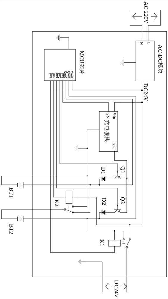
[0037] A battery charging and discharging circuit for an emergency power supply, such as Figure 1-Figure 2 As shown, including: AC-DC module, charging module, MCU chip, switch, conversion relay and battery, there is only one AC-DC module, charging module and MCU chip, and there are 2 switches, conversion relay and battery with the same number , the input terminal of the AC-DC module is connected to the mains, the output terminal of the AC-DC module is connected to the MCU chip, the input terminal of the charging module and the first conversion relay, and the output terminal of the first conversion relay is connected to the external load, charging The output terminal of the module is connected to the switch, the switch is connected to the battery, a conversion relay is connected between the two batteries, the second battery is also connected to the first conversion relay, and the MCU chip is also connected to the charging module, battery, switch and conversion relay. Relay con...

Embodiment 2

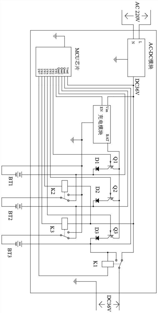
[0044] A battery charging and discharging circuit for an emergency power supply, such as Figure 3-Figure 4 As shown, including: AC-DC module, charging module, MCU chip, switch, conversion relay and battery, there is only one AC-DC module, charging module and MCU chip, and there are 3 switches, conversion relay and battery with the same number , the input terminal of the AC-DC module is connected to the mains, the output terminal of the AC-DC module is connected to the MCU chip, the input terminal of the charging module and the first conversion relay, and the output terminal of the first conversion relay is connected to the external load, charging The output terminal of the module is connected to the switch, the switch is connected to the battery, a conversion relay is connected between the two batteries, the third battery is also connected to the first conversion relay, and the MCU chip is also connected to the charging module, battery, switch and conversion relay. Relay conn...


PUM


Abstract

The invention provides a battery charging and discharging circuit of an emergency power supply. The battery charging and discharging circuit comprises an AC-DC module, a charging module, an MCU chip, a plurality of switches, a plurality of conversion type relays and a plurality of batteries, wherein the number of the switches, the number of the conversion type relays and the number of the batteries are the same, the output end of the AC-DC module is connected with the charging module and the first conversion type relay, the output end of the first conversion type relay is connected with an external load, the output end of the charging module is connected with the switches, the switches are connected with the batteries, one conversion type relay is connected between the two batteries, the nth battery is further connected with the first conversion type relay, and the MCU chip controls the switches and the conversion type relays to be turned on or turned off, so that the AC-DC module directly supplies power to the load, or / and charges the batteries through the charging module, or the batteries are connected in series to supply power to the load, or the charging and discharging abnormal protection of the batteries is achieved, wherein in the battery charging process, interval charging of the batteries is controlled through battery electric quantity signals monitored by the MCU chip so as to eliminate the difference of the electric quantity of the batteries.

Description

technical field [0001] The present invention relates to the technical field of electricity, and more specifically, relates to a battery charging and discharging circuit of an emergency power supply. Background technique [0002] Common fire-fighting lighting equipment includes A-type emergency lighting centralized power supply and EPS emergency power supply. When a fire, accident or other emergency occurs in a building, the fire-fighting lighting emergency power supply can provide emergency power supply for fire-fighting signs and lights. The main feature of Type A emergency lighting centralized power supply is that the output voltage is DC 24V or DC 36V. When the grid power supply is normal, the AC-DC module directly converts the 220V mains power into a low-voltage (24V or 36V) DC output to the load and charges the battery; when an emergency occurs, such as an abnormal grid power supply, the control module switches the output To the battery, the low-voltage DC output is ma...

Claims


Application Information

Patent Timeline
IPC IPC(8): H02J7/00H02J9/06
CPCH02J7/0014H02J7/0047H02J7/00712H02J9/06
Inventor 陈志敏杨烨
Owner 苏州新应期电子科技有限公司
Why Eureka
Try Eureka