
Embedded remote controller structure

A remote control and embedded technology, applied in the field of remote control, can solve problems such as inconvenient storage, affecting user experience, loss of remote control, etc., to achieve the effect of convenient storage and use, improved user experience, and convenient pick-and-place process

Pending Publication Date: 2022-01-21
FUJIAN MANEWAIOT LIGHTING CO LTD
View PDF0 Cites 0 Cited by
  • Summary
  • Abstract
  • Description
  • Claims
  • Application Information

AI Technical Summary

Problems solved by technology

However, the remote controllers of most existing electronic products basically exist independently from the structure of the product itself, which is inconvenient to store and is usually placed randomly, which can easily lead to the loss of the remote controller and affect the user experience.

Method used


Image

  • Embedded remote controller structure
  • Embedded remote controller structure
  • Embedded remote controller structure

Examples


Embodiment 1

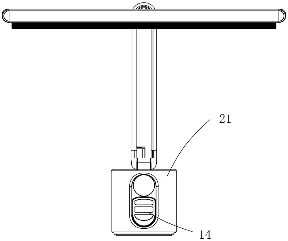
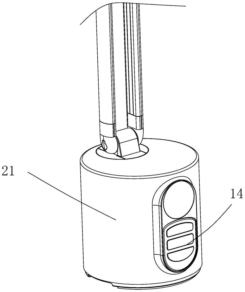
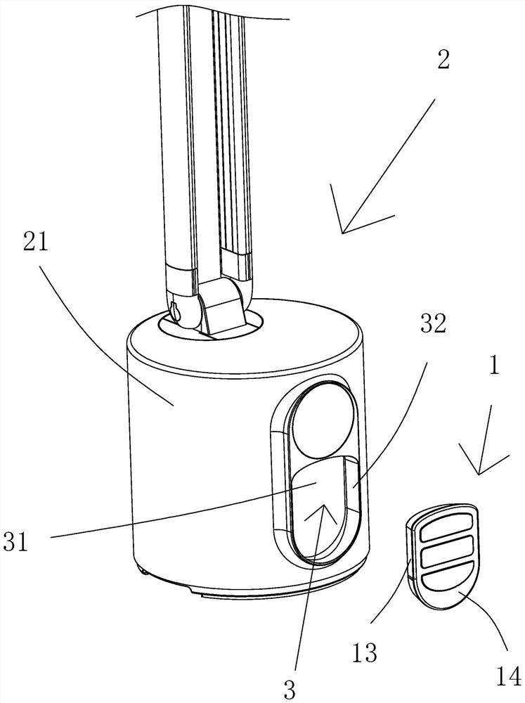
[0028] Such as Figure 1-7 As shown, an embedded remote control structure includes an electronic product body and a remote control 1. In this specific embodiment, the electronic product body is a piano light body 2, but it is not limited thereto. In some embodiments, the electronic product body It can also be other electronic products provided with remote controllers, such as smart desk lamps, smart TVs and the like.

[0029] The piano light body 2 includes a base 21. An open storage slot 3 is provided on the side of the base 21. The remote controller 1 is provided with a first magnetic attraction 11. The base 21 is provided with a second magnetic attraction 211. The remote controller 1 passes through the second magnetic attraction. The first magnetic piece 11 and the second magnetic piece 211 are mutually attracted and detachably arranged in the storage slot 3, so that the remote control 1 and the piano light body 2 are designed as one, the process of taking and placing is ex...

Embodiment 2

[0044] Such as Figure 8 As shown, the structure of this embodiment is roughly the same as that of Embodiment 1. The main difference is that in this embodiment, the bottom surface 31 of the storage tank 3 is a touch panel, and the touch panel is arranged in the storage tank 3 to make the product more compact. concise. Various existing touch panels can be used for the touch panel, which can be easily realized by those skilled in the art, and will not be described in detail here.

[0045] Further, in this embodiment, the inner side of the bottom surface 31 of the storage tank 3 is also provided with a magnetic induction unit 4, and the second magnetic member 211 is made of a soft magnetic material. In this specific embodiment, the second magnetic member 211 is preferably made of iron. Block to achieve, easy to implement, low cost, but not limited to this. The magnetic induction unit 4 is used to sense the magnetic field of the first magnetic attraction 11 to control whether th...


PUM


Abstract

The invention relates to the technical field of remote controllers, in particular to an embedded remote controller structure. The invention discloses an embedded remote controller structure which comprises an electronic product body and a remote controller, the electronic product body is provided with an open containing groove, the remote controller is provided with a first magnetic attraction part, the electronic product body is provided with a second magnetic attraction part, and the remote controller is detachably arranged in the containing groove through mutual attraction of the first magnetic attraction part and the second magnetic attraction part. The remote controller and the electronic product body are designed into a whole in a magnetic attraction fixing mode, the taking and placing process is extremely convenient, storage and use are convenient, the problem that the remote controller is prone to being lost is solved, user experience is improved, and the controller product is simple in structure, easy to implement and attractive.

Description

technical field [0001] The invention belongs to the technical field of remote controllers, and in particular relates to an embedded remote controller structure. Background technique [0002] With the rapid development of science and technology, many electronic products are becoming more and more intelligent, such as smart air conditioners, smart desk lamps, smart TVs, smart toilets, etc., and smart electronic products generally have a remote control design that integrates function keys The remote control can not only simplify the design of the product itself, but also increase the use range of the product in space, which greatly facilitates the use of the user. However, the remote controllers of most existing electronic products basically exist independently from the structure of the product itself, which is inconvenient to store and is generally placed randomly, which easily leads to the loss of the remote controller and affects the user experience. Contents of the invent...

Claims


Application Information

Patent Timeline
IPC IPC(8): H05K5/02G08C17/02
CPCH05K5/0217G08C17/02
Inventor 黄志鹏雷鹏陈慧娟
Owner FUJIAN MANEWAIOT LIGHTING CO LTD
Learn More