
Drying and conveying equipment with good effect for plate cutting

A technology for conveying equipment and plates, which is applied in the directions of wood drying, drying gas arrangement, lighting and heating equipment, etc. It can solve the problems of slow cutting efficiency, wet plates, and blackening of the cutting parts of the plates, so as to improve the sealing effect and improve the drying efficiency , The effect of easy access

Pending Publication Date: 2022-01-25
常州市智阳机械设备有限公司
View PDF0 Cites 2 Cited by
  • Summary
  • Abstract
  • Description
  • Claims
  • Application Information

AI Technical Summary

Problems solved by technology

At present, the long-term stacking of the boards purchased from the market will cause dampness. When cutting the boards, the boards need to be dried first. Secondly, the boards are cut manually, and the cutting efficiency is slow. At the same time, during the cutting process, there will be A large amount of heat is generated, the cutting part of the plate will turn black, and the cutting tool will be seriously damaged. If cooling water is used for cooling, the plate will be wet, and the plate after cutting needs to be dried again, which is time-consuming, laborious, inefficient, and expensive. Huge human and material resources
[0003] At the same time, after the cutting of the boards is completed, the cut boards need to be recycled and then packed. At present, after the boards are cut, they are manually transported to the collection box for collection and recycling. Due to the weight of the boards and The size is large, and it takes a lot of manpower and material resources to move the board, which is time-consuming and labor-intensive

Method used


Image

  • Drying and conveying equipment with good effect for plate cutting
  • Drying and conveying equipment with good effect for plate cutting
  • Drying and conveying equipment with good effect for plate cutting

Examples


Embodiment 1

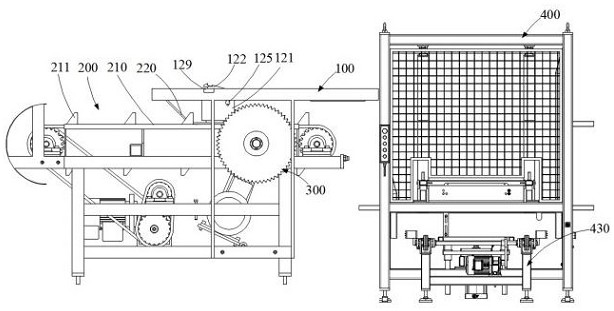
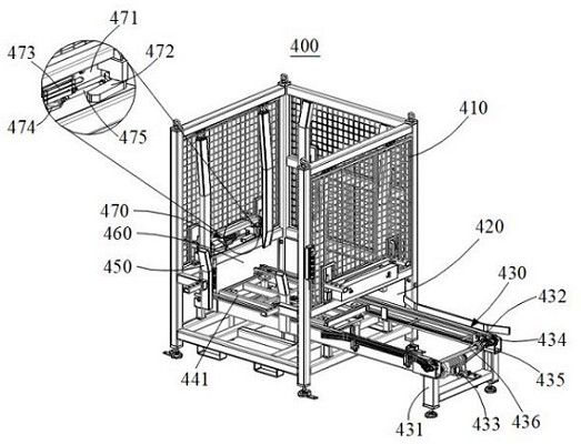
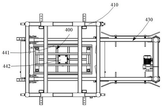
[0047] Such as Figure 1~6 As shown, a kind of dry conveying equipment for plate cutting with good effect, including,

[0048]The cutting system and the receiving system 400 arranged on one side of the cutting system, the receiving system 400 includes a collection box 410, a discharge port 420 provided on one side of the collection box 410 and a collection box 410 within the transfer section 430, and

[0049] The transmission part 430 includes a transmission frame 431, a transmission belt 432 arranged on both sides of the transmission frame 431, and a driving part for driving the transmission belt 432 to rotate; a lifting part 440 is also provided between the transmission frames 431, and the lifting The part 440 is adapted to lift the sheets in the collection box 410 to the top of the collection box 410;

[0050] The cutting system includes a first conveying unit 100, the first conveying unit 100 includes a support 110, a cooling unit 120 arranged on the support 110 and a dr...


PUM


Abstract

The invention relates to the technical field of drying, in particular to drying and conveying equipment with a good effect for plate cutting. The equipment comprises a cutting system and a material collecting system arranged on one side of the cutting system, the material collecting system comprises a collecting box, a discharge port formed in one side of the collecting box and a conveying part arranged in the collecting box, and the conveying part comprises a conveying frame, conveying belts arranged on the two sides of the conveying frame and a driving part for driving the conveying belts to rotate. By arranging the collecting box and the conveying part, plates cut by the cutting system are conveyed into the collecting box and then conveyed out from the discharge port of the collecting box; meanwhile, a lifting part is further arranged, the plates at the bottom of the collecting box can be conveyed to the uppermost end, manual taking is convenient, the structure is simple, and efficiency is high; and the lifting part cooperates with a pressing part so that the plates in the collecting box can be pressed.

Description

technical field [0001] The invention relates to the field of drying technology, in particular to a drying conveying device for plate cutting with good effect. Background technique [0002] Plates are an important material, and they need to be stored, but the sizes of plates supplied on the market are inconsistent, which cannot meet the storage requirements. Therefore, it is necessary to cut the plates purchased in the market and then store them. At present, the long-term stacking of the boards purchased from the market will cause dampness. When cutting the boards, the boards need to be dried first. Secondly, the boards are cut manually, and the cutting efficiency is slow. At the same time, during the cutting process, there will be A large amount of heat is generated, the cutting part of the plate will turn black, and the cutting tool will be seriously damaged. If cooling water is used for cooling, the plate will be wet, and the plate after cutting needs to be dried again, w...

Claims


Application Information

Patent Timeline
IPC IPC(8): B26D1/15B26D7/00B26D7/06B26D7/08B26D7/32B26D7/18F26B21/00
CPCB26D1/15B26D7/00B26D7/0625B26D7/06B26D7/08B26D7/088B26D7/32B26D7/1854F26B21/004F26B2210/16B26D2007/0018Y02P70/10
Inventor 阳廷春李智
Owner 常州市智阳机械设备有限公司
Learn More