Tempered photovoltaic vacuum glass structure
A vacuum glass and photovoltaic technology, applied in photovoltaic power generation, electrical components, circuits, etc., can solve the problems of surface compressive stress decline of tempered glass, photovoltaic glass performance attenuation, photovoltaic glass power generation performance attenuation and other problems
Pending Publication Date: 2022-01-25
青岛达城真空玻璃科技发展有限公司
View PDF5 Cites 1 Cited by
- Summary
- Abstract
- Description
- Claims
- Application Information
AI Technical Summary
Problems solved by technology
[0005] In addition, in order to form a vacuum layer between the two glass substrates, usually through the edge sealing process, so that these glass substrates can be in an airtight state, the inventor found that in the edge sealing process, due to these glass substrates (that is, Tempered glass) will be sent into a heating device for high-temperature baking. At this time, under the influence of high temperature, the compressive stress on the surface of the tempered glass and the performance of the photovoltaic glass will decline. After testing by the inventor, the tempered glass after decay , the compressive stress on its surface is about twice that of ordinary glass, almost equal to that of semi-tempered glass (or heat-treated reinforced glass), that is, after the edge-sealing process, the original overall strength of the vacuum glass
Method used
View moreImage
Smart ImageViewing Examples
Examples
 PUM
 Abstract
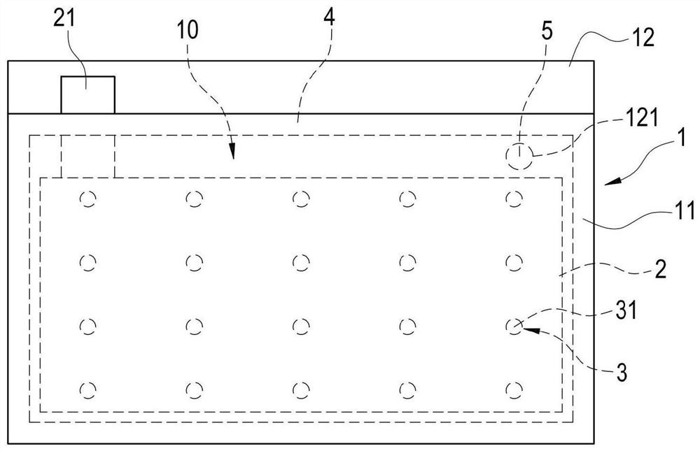
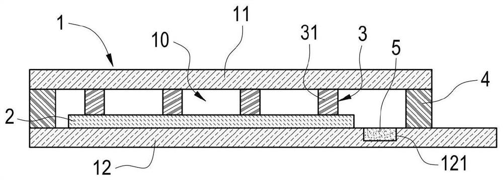
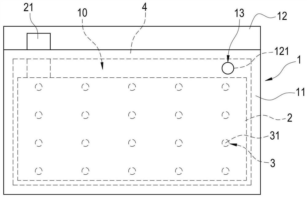
The invention discloses a tempered photovoltaic vacuum glass structure. The tempered photovoltaic vacuum glass structure comprises a glass substrate, a photovoltaic element, a supporting object, an edge sealing material and a getter. The glass substrate comprises an upper glass substrate and a lower glass substrate. The photovoltaic element is arranged on the surface of one side of the lower glass substrate, and the photovoltaic element is electrically connected with an electrode lead. The supporting object is composed of a plurality of supporting columns and arranged between the upper glass substrate and the lower glass substrate. The edge sealing material is arranged between two corresponding side surfaces of the upper glass substrate and the lower glass substrate and is only adjacent to the peripheral positions of the upper glass substrate and the lower glass substrate so as to form a vacuum area. The getter is disposed adjacent to the photovoltaic element on a side surface of the lower glass substrate. The edge sealing material adopts low-temperature glass cement, the width of the edge sealing material after edge sealing is more than 3mm, and a gap of more than 1mm is formed between the photovoltaic element and the edge sealing material, so that part of the electrode lead extends out of the vacuum area.
Description
technical field [0001] The invention relates to a toughened photovoltaic vacuum glass structure, in particular to a toughened photovoltaic vacuum glass structure using laser heating edge sealing technology. Background technique [0002] Most of the current BIPV architectural photovoltaic glass uses a single photovoltaic substrate and another piece of glass to form a laminated glass or the component and another piece of glass to form a photovoltaic insulating glass. The laminated glass does not have heat insulation performance, while the insulating glass is in two An air layer is formed between the glass substrates. Because the heat energy in the air is more difficult to transmit than glass, the heat insulation effect of insulating glass will be better than that of ordinary glass or laminated glass, but the insulating glass Gas still has heat conduction and convection, which makes its heat insulation ability still not ideal. Vacuum glass forms a vacuum layer between two glass...
Claims
Login to View More Application Information
Patent Timeline
 IPC IPC(8): C03C27/10H01L31/048
CPCC03C27/10H01L31/0488H01L31/0481Y02E10/50
Inventor 化山刘成伟徐志武秦海
Owner 青岛达城真空玻璃科技发展有限公司
Features
- R&D
- Intellectual Property
- Life Sciences
- Materials
- Tech Scout
- Unparalleled Data Quality
- Higher Quality Content
- 60% Fewer Hallucinations
Learn More Browse by: Latest US Patents, China's latest patents, Technical Efficacy Thesaurus, Application Domain, Technology Topic, Popular Technical Reports.
© 2025 PatSnap. All rights reserved.Legal|Privacy policy|Modern Slavery Act Transparency Statement|Sitemap|About US| Contact US: help@patsnap.com


