Separated drill point guider
A guide and separate technology, applied in dental drilling, medical science, dentistry, etc., can solve the problems of constant carrying, large space occupation, non-detachable, etc., to achieve enhanced comfort, small occupation space, and increased stability Effect
- Summary
- Abstract
- Description
- Claims
- Application Information
AI Technical Summary
Problems solved by technology
Method used
Image

Examples
Embodiment 1
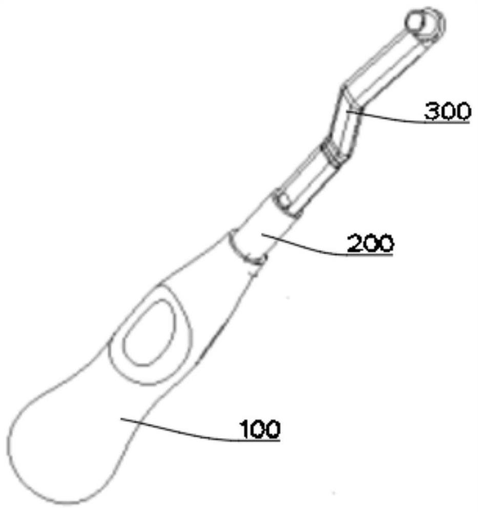
[0028] see Figure 1~3 , in Embodiment 1 of the present invention, it is a structural diagram of a separate drill guide provided by the embodiment of the present invention, including: a handle 100, an adapter 200 and a guide 300; between the adapter 200 and the handle 100 It is fixed by the card slot, so as to prevent rotation or offset and increase stability; the upper and lower ends of the card slot have a tapered design for easy taking out and putting in;
[0029] There is a hollow groove at the center of the handle 100, which is used to put a magnet for magnetic attraction in the later stage, and a cylindrical groove is left in the center of the adapter 200 for fixing so that it can just closely contact with the hollow groove of the magnet.
[0030] The joint between the guide 300 and the adapter 200 is connected by a multi-edged card slot, which is used to fix the position to prevent deflection and displacement.
Embodiment 2
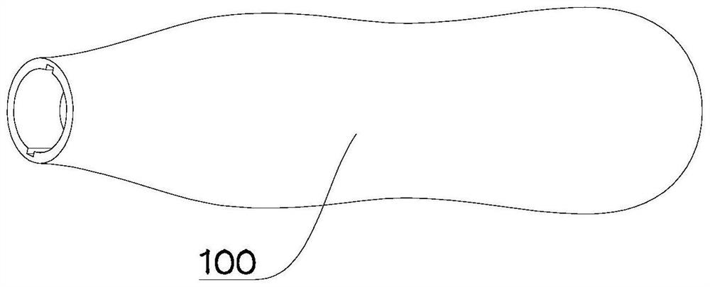
[0032] see Figure 2~3 The main difference between this embodiment 2 and embodiment 1 is that the handle 100 adopts a spline curve as a whole, and adopts an ergonomic design to increase the stability of the palm; The arc is provided to increase the hand feeling when holding. One end of the handle 100 adopts a magnetic connection method for placing magnets later, and the handle 100 and the guide 300 have better and closer contact through the adapter 200 .
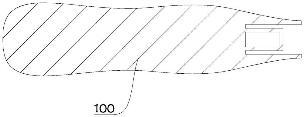
[0033] The handle 100 is connected to the adapter 200 so that the handle 100 is in closer contact with the guide 300. The handle 100 is connected to the center of the end of the adapter 200 to place a magnet for magnetic attraction. The handle 100 is connected to the end of the adapter 200, and the end is provided with a plurality of protrusions as slots for fixing the adapter 200 to prevent the adapter 200 from rotating or shifting.
[0034] Such as Figure 4-6 As shown, as another preferred embodiment of the present inve...
PUM
 Abstract
Description
Claims
Application Information
 - R&D
- Intellectual Property
- Life Sciences
- Materials
- Tech Scout
- Unparalleled Data Quality
- Higher Quality Content
- 60% Fewer Hallucinations
Browse by: Latest US Patents, China's latest patents, Technical Efficacy Thesaurus, Application Domain, Technology Topic, Popular Technical Reports.
© 2025 PatSnap. All rights reserved.Legal|Privacy policy|Modern Slavery Act Transparency Statement|Sitemap|About US| Contact US: help@patsnap.com