Rehabilitation training equipment for spine
A rehabilitation training and spine technology, applied in passive exercise equipment, physical therapy and other directions, can solve the problems of inconvenient use and poor training effect of patients, and achieve the effect of reducing spinal stress, good training effect and easy to use.
- Summary
- Abstract
- Description
- Claims
- Application Information
AI Technical Summary
Problems solved by technology
Method used
Image

Examples
Embodiment
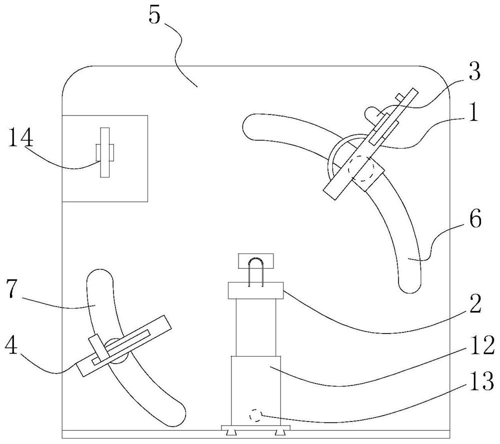
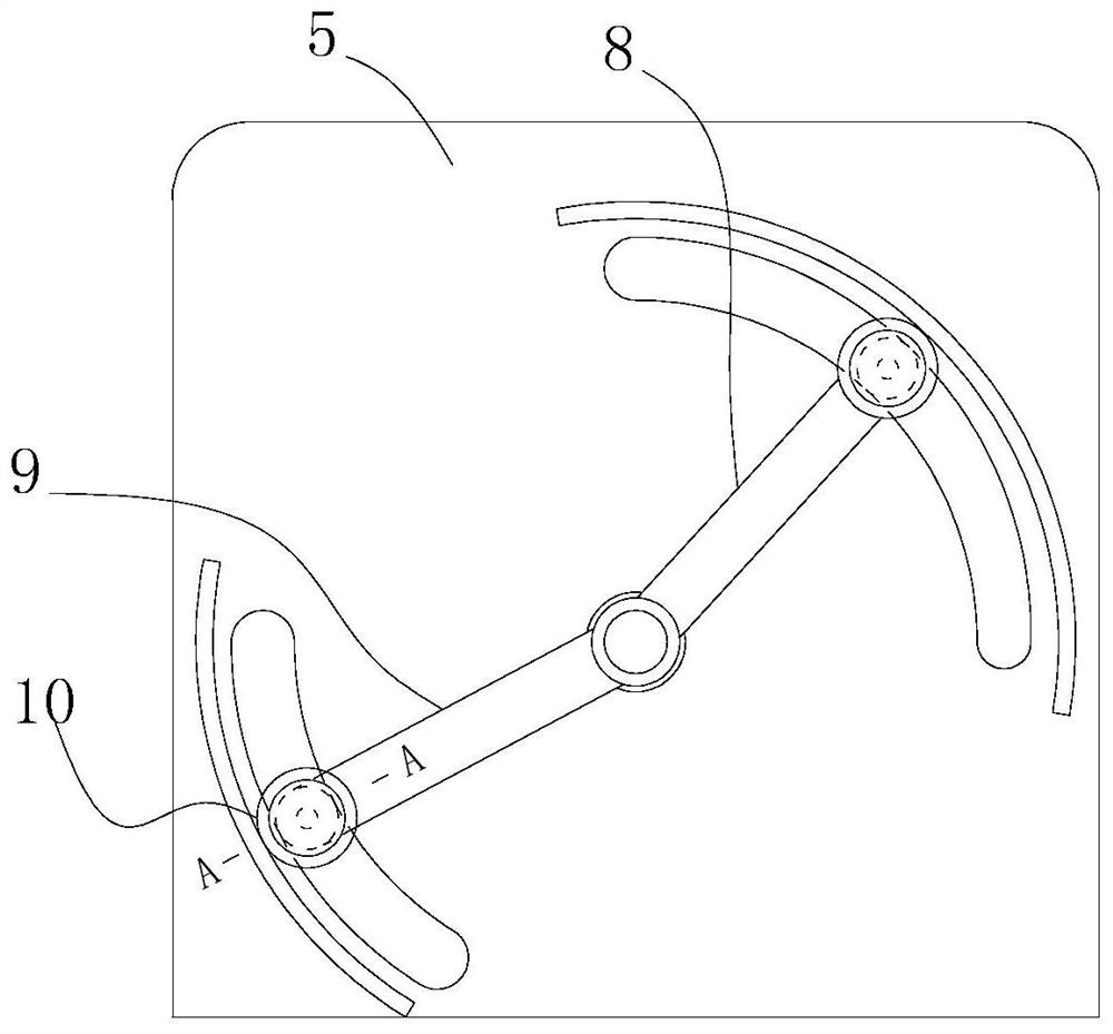
[0038] Such as figure 1 , figure 2As shown, a kind of rehabilitation training equipment for the spine according to the present invention includes a back fixing device 1, a mobile seat 2, a head support device 3, a foot support device 4, and a support 5, and the support 5 is used for Carry the back fixing device 1, the mobile seat 2, and the foot support device 4. The bottom of the mobile seat 2 is slidably connected to the support 5 and can move forward and backward. The back fixing device 1 and the foot support device 4 can all be placed on the support 5 to make an arc movement; the lower end of the mobile seat 2 is connected with the first electric telescopic rod 12, and the bottom end of the first electric telescopic rod 12 is connected with a bottom plate, and the bottom plate is connected to the support 5 through the slide rail chute 402 structure, the second The lower end of an electric telescopic rod 12 is provided with the second electric telescopic rod 13, and the t...
PUM
 Abstract
Description
Claims
Application Information
 - R&D
- Intellectual Property
- Life Sciences
- Materials
- Tech Scout
- Unparalleled Data Quality
- Higher Quality Content
- 60% Fewer Hallucinations
Browse by: Latest US Patents, China's latest patents, Technical Efficacy Thesaurus, Application Domain, Technology Topic, Popular Technical Reports.
© 2025 PatSnap. All rights reserved.Legal|Privacy policy|Modern Slavery Act Transparency Statement|Sitemap|About US| Contact US: help@patsnap.com