Eureka AIR delivers breakthrough ideas for toughest innovation challenges, trusted by R&D personnel around the world.

Mold

A technology of molds and snap-fit ​​parts, which can be applied to household appliances, other household appliances, tires, etc., and can solve problems such as damage, sector deformation, and snap-fit ​​pin deformation.

Pending Publication Date: 2022-01-28
SUMITOMO RUBBER IND LTD
View PDF1 Cites 0 Cited by
  • Summary
  • Abstract
  • Description
  • Claims
  • Application Information

AI Technical Summary

Problems solved by technology

This large external force sometimes deforms the engaging pin and breaks it.
And, this larger external force may deform the sector for the protruding engaging pin.

Method used


Image

  • Mold
  • Mold
  • Mold

Examples


Embodiment

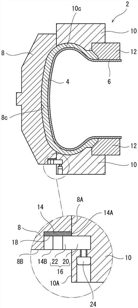
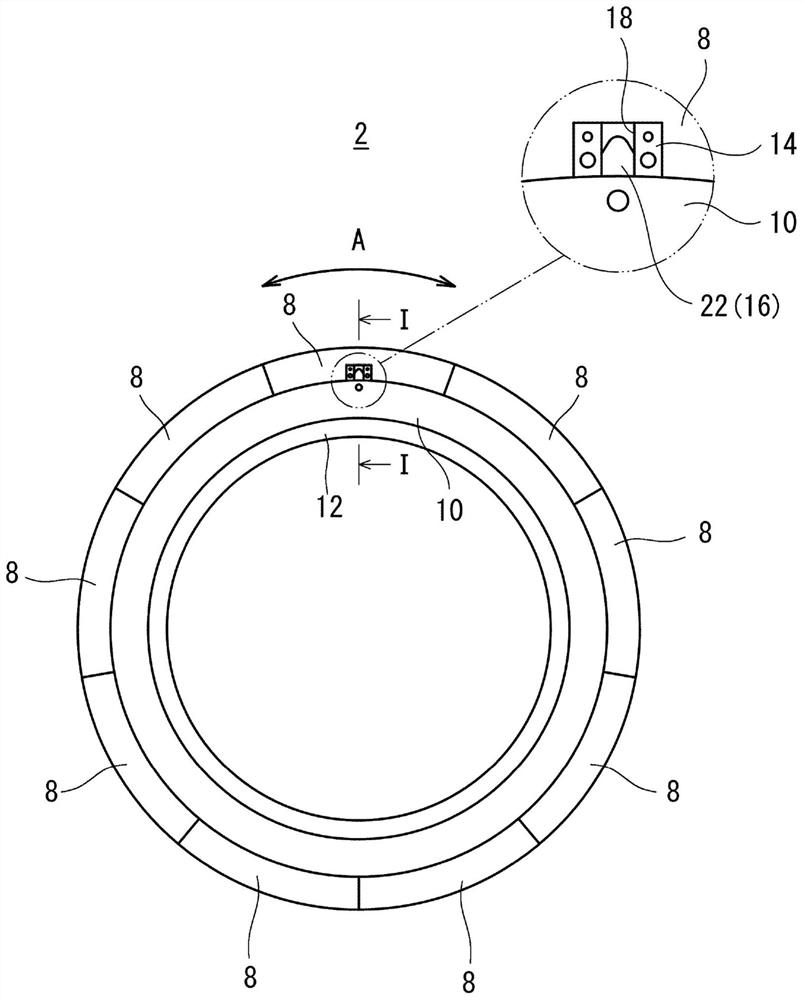
[0077] get ready figure 1 mold. The mold has 9 sectors. A first engaging part is fixed on the lower side of the first sector part arranged along the circumferential direction. In addition, a third engaging member identical to the first engaging member is fixed on the upper side of the fifth sector arranged along the circumferential direction. A second engaging piece engaged with the first engaging piece is fixed to one of the pair of side plates (the lower side plate). On the other side (upper side plate), a fourth engaging member similar to the second engaging member engaged with the third engaging member is fixed. Other parts are the same as the existing mould. Use this mold to make 1400 tires.

[0078] [Example]

[0079] 1,400 tires were manufactured in the same manner as in the examples except that the existing dies were used.

[0080] [evaluation of position shift]

[0081] 15 tires were randomly selected out of every 100 manufactured tires of the examples. For t...


PUM


Abstract

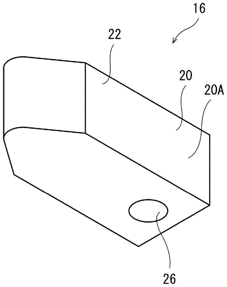
Provided is a mold capable of suppressing positional displacement in the circumferential direction. The mold (2) has: a plurality of sectors (8) that mold the tread of a tire; a first side plate (10) that molds one of a pair of sidewall outer surfaces of the tire; a first engagement member (14) that is fixed to the sectors (8); and a second engagement member (16) that is fixed to the first side plate (10), has a hardness (H2) that is less than the hardness (H1) of the first engagement member (14), and can engage with the first engagement member (14).

Description

technical field [0001] The present invention relates to a mold for tires. Background technique [0002] In the tire manufacturing method, a green tire is put into a tire mold, and the green tire is pressurized and heated to obtain a tire from the green tire. As one type of such a mold, there is a mold that has a sector for molding a tread and a pair of side plates for molding a sidewall outer surface, respectively. [0003] In this die, the sectors and the side plates may be misaligned in the circumferential direction. This circumferential positional shift causes a positional shift between the tread of the tire and the sidewall outer surface. In particular, in tires having a pattern of grooves or blocks or the like across the tread and the outer surface of the sidewall, its appearance suffers. [0004] Patent Document 1 discloses a mold in which an engaging pin protruding from a sector is engaged with a groove of a side plate so that the sector and the side plate are posi...

Claims


Application Information

Patent Timeline
IPC IPC(8): B29C33/38B29C35/02B29L30/00
CPCB29C33/38B29C35/02B29L2030/00
Inventor 新川耕司山田吉博
Owner SUMITOMO RUBBER IND LTD
Why Eureka
Eureka Blog
Learn More