Multifunctional field engineering vehicle

A kind of engineering vehicle and multi-functional technology, applied in the direction of cranes, etc., can solve the problems of low construction efficiency, many types and coordination links, high cost of equipment use and deployment, and achieve the effect of improving work efficiency, compact structure and simple operation

Pending Publication Date: 2022-01-28
SINOPEC SSC +1
View PDF0 Cites 0 Cited by
  • Summary
  • Abstract
  • Description
  • Claims
  • Application Information

AI Technical Summary

Problems solved by technology

[0004] In order to solve the problems of high equipment use and deployment costs and low construction efficiency due to the many types and coordination links of existing field engineering equipment, this application proposes a multifunctional field engineering vehicle

Method used


Image

  • Multifunctional field engineering vehicle

Examples


Embodiment Construction

[0027] The present invention will be further described below in conjunction with accompanying drawing.

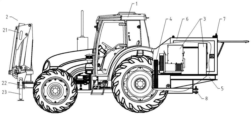
[0028] The present invention provides a multifunctional field engineering vehicle, comprising a vehicle body 1, on which functional components are arranged, the functional components include a crane 2 and a power generating device 3, the crane 2 is arranged on the head of the vehicle body 1, and the power generating device 3 is arranged at the tail of the vehicle body 1;

[0029] The vehicle body 1 is also provided with a transmission component 4 , the power input end of the transmission component 4 is connected to the power source of the vehicle body 1 , and the power output end of the transmission component 4 is respectively connected to the crane 2 and the power generation device 3 .

[0030] Specifically, as shown in the attached figure 1 As shown, the engineering vehicle of the present invention mainly includes a vehicle body 1 and functional parts arranged on the veh...


PUM


Abstract

The invention provides a multifunctional field engineering vehicle which comprises a vehicle body, functional parts are arranged on the vehicle body, the functional parts comprise a crane and a power generation device, the crane is arranged at the head of the vehicle body, and the power generation device is arranged at the tail of the vehicle body; the vehicle body is further provided with a transmission part, the power input end of the transmission part is connected with a power source of the vehicle body, and the power output end of the transmission part is connected with the crane and the power generation device. Based on the technical scheme, an integrated self-propelled power supply and hoisting and traction equipment are provided for field construction, the vehicle has the advantages of being convenient to use, compact in structure, capable of saving energy, high in working efficiency, easy to operate, safe and reliable, and the working efficiency of field operation is greatly improved.

Description

technical field [0001] The invention relates to the technical field of engineering operation equipment, in particular to a multifunctional field engineering vehicle. Background technique [0002] In the current field construction process, the power supply and the hoisting and traction movement of common equipment are in a separate state, and different equipment needs to be used for operation. The power supply for power supply needs to be dragged by a trailer, and some equipment needs to be transported by vehicles. A construction unit needs to be equipped with or use multiple types of cranes. There are problems of inconvenient construction and low work efficiency, and a large amount of resources and energy are wasted. [0003] Moreover, due to the large number of construction equipment types and coordination links, the use and deployment costs of construction equipment are high, the safety is low, and the failure rate is high. The overall efficiency of the equipment is about...

Claims


Application Information

Patent Timeline
IPC IPC(8): B66C23/44B66C23/40
CPCB66C23/44B66C23/40
Inventor 艾国山刘长志刘庆林李思瑶高正扬王红旗相军滕玉萍常秀梅方炉平
Owner SINOPEC SSC
Why Eureka
Try Eureka