Off-axis optical module and head-mounted display device
What is AI technical title?
AI technical title is built by Patsnap AI team. It summarizes the technical point description of the patent document.
An optical module, off-axis technology, applied in the direction of optics, optical components, instruments, etc., can solve the problems of structural interference, increase the difficulty of design and manufacturing, waste of lenses, etc., and achieve the effect of large magnification
Pending Publication Date: 2022-01-28
BEIJING NEDPLUSAR DISPLAY TECH CO LTD
View PDF2 Cites 1 Cited by
Summary
Abstract
Description
Claims
Application Information
AI Technical Summary
This helps you quickly interpret patents by identifying the three key elements:
Problems solved by technology
Method used
Benefits of technology
Problems solved by technology
However, the multiple lenses placed off-axis to each other used in the off-axis reflection module, on the one hand, increase the design and manufacturing difficulty of the structural parts that match with the optical module, on the other hand, only some areas of some lenses Through the light, there is a waste of the lens
[0004] In addition, in the optical design scheme of the existing off-axis reflection imaging technology, the inclination angle of the curved mirror used is generally relatively small, generally within 30°, which makes this kind of scheme easy to exist in the helmet display system. Problems with Structural Interference
Method used
Image
Click on the blue label to locate the original text in one second.
Reading with bidirectional positioning of images and text.
Examples
no. 1 example
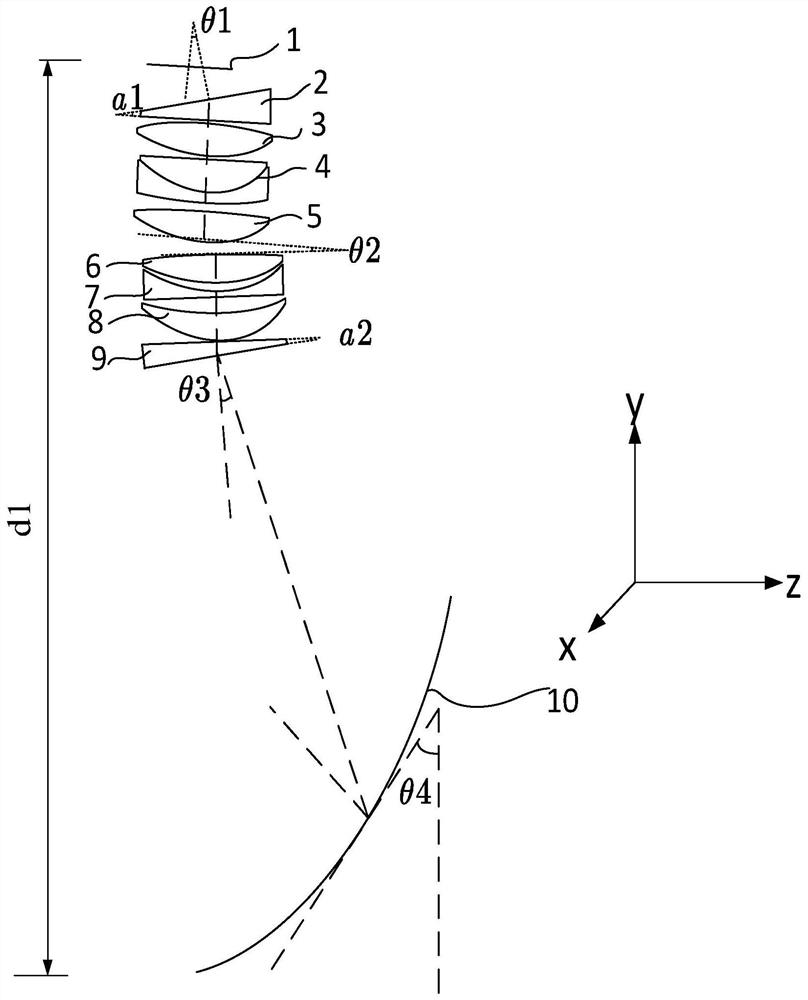
[0041] In the first embodiment, the structure of the off-axis optical module is as figure 2 As shown, it includes image source 1, first wedge prism 2, first lens 3, positive-negative doublet lens 4, second lens 5, third lens 6, fourth lens 7, fifth lens 8, second Wedge prism 9 and curved mirror 10.
[0042] Wherein, the first wedge prism 2 , the first lens 3 , the positive-negative doublet lens 4 , and the second lens 5 form the first lens group 20 . The mechanical axes (defined as the first axis A) of the first wedge prism 2 , the first lens 3 , the positive-negative doublet lens 4 , and the second lens 5 coincide and are arranged coaxially.
[0043] The first lens group 20 may be a group of coaxial spherical, cylindrical, aspheric, and free-form lenses. Preferably, in order to effectively correct the systemchromatic aberration, the first lens group 20 includes a positive-negative doublet lens. Preferably, in order to correct high-order aberrations, a convex lens with as...
no. 2 example
[0056] Such as Figure 4 The shown off-axis optical module includes an image source 1, a first wedge prism 2, a first lens 3, a positive-negative doublet lens 4, a second lens 5, a third lens 6, a fourth lens 7, a first Five lenses 8, reflecting mirrors 11 and curved mirrors 10.
[0057] Wherein, the first wedge prism 2 , the first lens 3 , the positive-negative doublet lens 4 , and the second lens 5 form the first lens group 20 . The mechanical axes (defined as the first axis A) of the first wedge prism 2 , the first lens 3 , the positive-negative doublet lens 4 , and the second lens 5 coincide and are arranged coaxially.
[0058] The first lens group 20 may be a group of coaxial spherical, cylindrical, aspheric, and free-form lenses. Preferably, in order to effectively correct the system chromatic aberration, the first lens group 20 includes a positive-negative doublet lens. Preferably, in order to correct high-order aberrations, a convex lens with aspheric surfaces is se...
PUM
Abstract
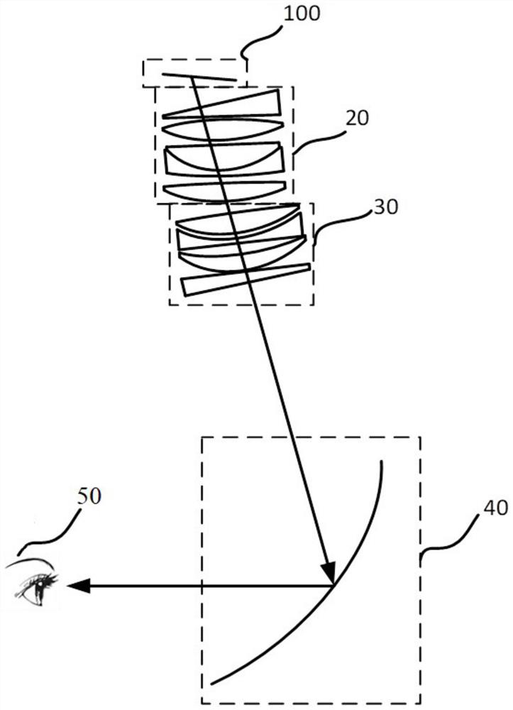
The invention discloses an off-axis optical module comprising a first lens group, a second lens group and a curved mirror; the first lens group is used for receiving image light from a micro display in an off-axis mode; the first lens group comprises a plurality of lenses, and the plurality of lenses in the first lens group are coaxially arranged; the first lens group further comprises a first wedge-shaped prism; the first wedge-shaped prism is arranged at a position close to the image source relative to the plurality of lenses in the first lens group; the second lens group is used for receiving the image light passing through the first lens group; the second lens group comprises a plurality of lenses coaxially arranged; the first lens group and the second lens group are arranged in a mutually off-axis manner, and the first lens group and the second lens group form a relay optical system; and the image light passing through the first lens group and the second lens group forms an intermediate image surface, and then is reflected by the curved mirror to enter human eyes. The invention further provides a head-mounted display device comprising the off-axis optical module.
Description
technical field [0001] The present invention relates to an off-axis optical module, and also relates to a head-mounted display device comprising the above-mentioned off-axis optical module. Background technique [0002] The main feature of augmented reality technology is to superimpose virtual information on the real scene to realize the enhancement of reality. Augmented reality technology can integrate virtual information (such as objects, pictures, videos, sounds, etc.) into the real environment, enrich the real world, and build a more comprehensive and better world. With the gradual entry of wearable devices into people's careers and lives in recent years, especially the development of the smart glasses industry, the distance between people and augmented reality technology has taken a step further. [0003] At present, augmented reality technology has made great progress on the helmet image display device. Among them, some products use off-axis reflection imaging techno...
Claims
Application Information
Patent Timeline
Application Date:The date an application was filed.
Publication Date:The date a patent or application was officially published.
First Publication Date:The earliest publication date of a patent with the same application number.
Issue Date:Publication date of the patent grant document.
PCT Entry Date:The Entry date of PCT National Phase.
Estimated Expiry Date:The statutory expiry date of a patent right according to the Patent Law, and it is the longest term of protection that the patent right can achieve without the termination of the patent right due to other reasons(Term extension factor has been taken into account ).
Invalid Date:Actual expiry date is based on effective date or publication date of legal transaction data of invalid patent.

