Special bracket for obstetrics and gynecology surgical instruments

A kind of surgical equipment, obstetrics and gynecology technology, applied in the field of brackets, can solve the problems of large space occupation, poor practicability, adverse effects of medical staff's position, etc., and achieve the effect of improving stability, convenient installation and disassembly, and strong practicability

Pending Publication Date: 2022-02-01
牛瑞霞
View PDF0 Cites 0 Cited by
  • Summary
  • Abstract
  • Description
  • Claims
  • Application Information

AI Technical Summary

Problems solved by technology

[0003] The current surgical instrument brackets all use the structure of the support frame to cooperate with the tray. Generally, the tray and the support frame are installed in an unfixed manner, and universal wheels will be installed at the bottom of the support frame to move the ...

Method used


Image

  • Special bracket for obstetrics and gynecology surgical instruments
  • Special bracket for obstetrics and gynecology surgical instruments
  • Special bracket for obstetrics and gynecology surgical instruments

Examples


Embodiment 1

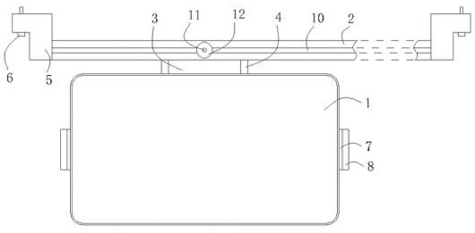
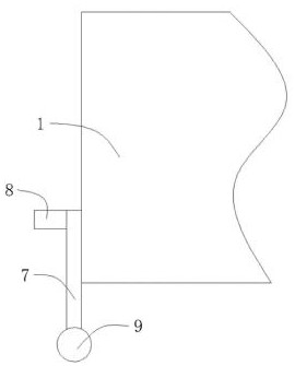
[0024] like Figure 1 to Figure 3 As shown, the special bracket for obstetrics and gynecology surgical equipment in this embodiment includes a tray 1 and a slide rail 2, a slide block is slidably installed on the slide rail 2, and a U-shaped plate 4 is installed on the slide block, so that the U-shaped plate 4 can Sliding along the slide rail 2, and a slot is formed between the U-shaped plate 4 and the slider, and a latch plate 3 is installed on the outer wall of the tray 1, and the latch plate 3 cooperates with the plug formed between the U-shaped plate 4 and the slider. slot, so that when installing the tray 1, it is only necessary to place the tray 1 flat, and then insert the latch plate 3 into the slot, and the latch plate 3 is inserted into the slot, and by setting the slide rail 2 and the slider, And the U-shaped plate 4 is installed on the slider, which not only facilitates the installation and disassembly of the tray 1, but also solves the problem that the traditional ...

Embodiment 2

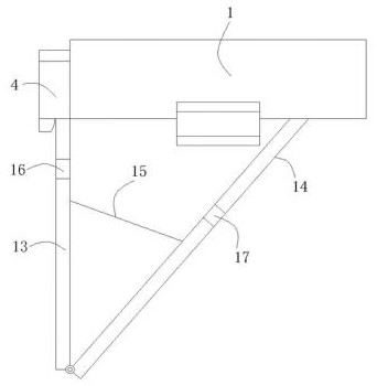
[0032] The structure of the dedicated bracket for obstetrics and gynecology surgery equipment in this embodiment is basically the same as that of the bracket for obstetrics and gynecology surgery equipment in Embodiment 1. The difference is that the end of support rod two 14 away from support rod one 13 passes through the damping shaft A strip plate 18 is movably connected, and the upper surface of the strip plate 18 is provided with a rubber pad (see Figure 4 ). The strip plate 18 is movably connected to the end of the support rod two 14 away from the support rod one 13 through the damping shaft, on the one hand, the contact area between the support rod two 14 and the bottom surface of the tray 1 is increased, and the stability of the tray 1 is further improved. On the one hand, it is also possible to achieve complete contact between the upper surface of the strip plate 18 and the pallet 1 .

[0033] The usage method of this embodiment is as follows: first use the mounting ...


PUM


Abstract

The invention discloses a special bracket for obstetrics and gynecology surgical instruments, and belongs to the technical field of obstetrics and gynecology surgical instruments, wherein the bracket comprises a tray and a sliding rail; a sliding block is slidably mounted on the sliding rail, a U-shaped plate is mounted on the sliding block, a slot is formed between the U-shaped plate and the sliding block, and a pin plate is mounted on the outer wall surface of the tray; the pin plate is inserted into the inside of the slot; the sliding rail is provided with a positioning mechanism used for fixing the position of the sliding block, and the bottom of the U-shaped plate is provided with a supporting mechanism; and the positioning mechanism comprises a screw rod and a nut, the upper surface of the sliding rail is provided with a strip-shaped groove, and one end of the screw rod penetrates through the strip-shaped groove and is connected with the sliding block. By arranging the sliding rail and the sliding block and mounting the U-shaped plate on the sliding block, the tray is convenient to mount and dismount, the problems that a traditional bracket occupies a large space and the standing position of medical staff is affected are solved, rapid and smooth completion of an operation is facilitated, and the practicability is high.

Description

technical field [0001] The invention relates to the technical field of brackets, in particular to a dedicated bracket for obstetrics and gynecology surgical equipment. Background technique [0002] Obstetrics and gynecology is one of the four main disciplines of clinical medicine. Surgical instruments during obstetrics and gynecology operations need to be placed on brackets for easy access during operations. [0003] The current surgical instrument brackets all use the structure of the support frame to cooperate with the tray. Generally, the tray and the support frame are installed in an unfixed manner, and universal wheels will be installed at the bottom of the support frame to move the bracket. However, due to the current The bracket itself takes up a lot of space and needs to be placed on the ground, which may adversely affect the standing position of medical staff, and removing it is not conducive to the taking and use of surgical instruments, and has poor practicability...

Claims


Application Information

Patent Timeline
IPC IPC(8): A61B50/33A61G13/10
CPCA61B50/33A61G13/101
Inventor 牛瑞霞
Owner 牛瑞霞
Why Eureka
Try Eureka