Sliding loading machine

A skid steer loader and hinged technology, which is applied to earth movers/shovels, mechanically driven excavators/dredgers, construction, etc. problems, to achieve the effect of increasing the maintenance area, shortening the width of the machine, and reliable work efficiency

Pending Publication Date: 2020-04-10
SUNWARD INTELLIGENT EQUIP CO LTD
View PDF0 Cites 4 Cited by
  • Summary
  • Abstract
  • Description
  • Claims
  • Application Information

AI Technical Summary

Problems solved by technology

[0004] The technical problem solved by the present invention is to provide a new type of skid steer loader for the problem of poor work efficiency due to the difficulty of disassembly and maintenance of the existing skid steer loader

Method used


Image

  • Sliding loading machine
  • Sliding loading machine
  • Sliding loading machine

Examples


Embodiment 1

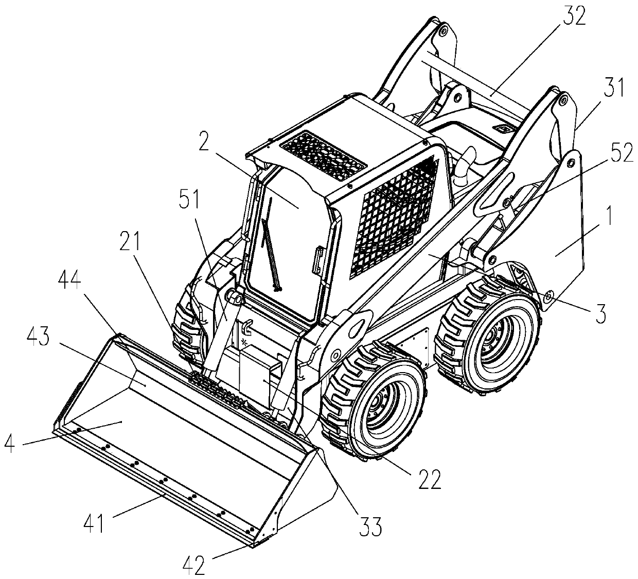
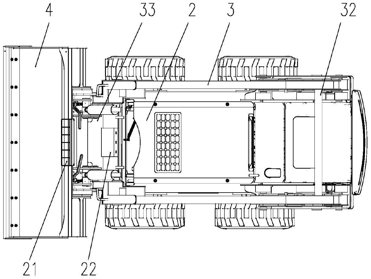
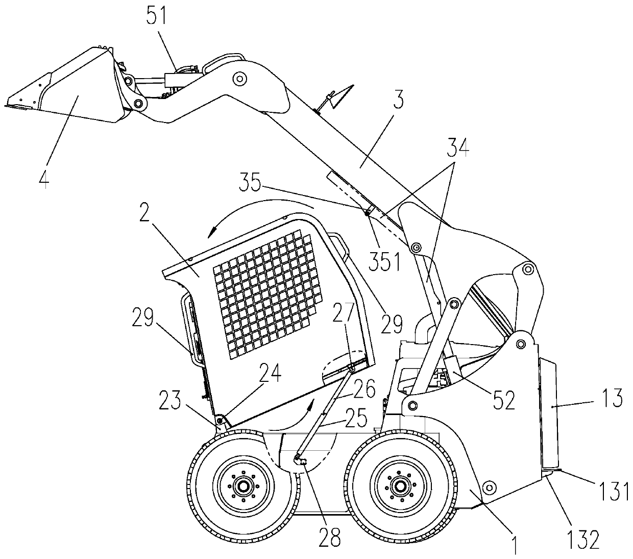
[0062] see Figure 1-3 , the skid steer loader in the illustration is a specific embodiment of the present invention, specifically including a chassis frame 1, a cab 2, a main beam 3, a bucket 4, a loading and unloading cylinder 51, a lifting cylinder 52 and the power system in the figure Not shown, etc., wherein, the chassis frame 1 is assembled with the wheeled walking system to form the mobile chassis of the skid steer loader. The hydraulic motor control can realize the walking and steering functions of the skid steer loader through the speed difference of the wheels on both sides. The power system includes the engine system and the hydraulic system, and the various action parts of the skid steer loader provide driving force. The driver's cab 2 is flipped and set at the front of the chassis frame 1 for the driver to operate the skid steer loader. The main beam 3 connects the bucket 4 and the chassis frame 1, and transmits the lifting power of the bucket 4 through the swing ...

Embodiment 2

[0083] see Figure 16 , the skid steer loader in the illustration is another specific embodiment of the present invention. The skid steer loader in the first embodiment uses a wheeled walking system. This embodiment is on the same chassis frame as the first embodiment Equipped with crawler walking system. According to the setting position of the crawler walking system, it can be completed by replacing the wheel axle bracket with the crawler frame. Compared with the wheel-type walking system, the crawler-type walking system has a more stable load balance in the loading and unloading movement of the vehicle, and a stronger cross-country driving ability.


PUM


Abstract

The invention discloses a sliding loading machine. A chassis frame, a cab, a main beam and a bucket are included. The chassis frame and a walking system are assembled to form a moving chassis of the sliding loading machine, and a power system of the sliding loading machine is assembled to the tail of the chassis frame. The cab is arranged at the front portion of the chassis frame in an overturnedmanner. The cab is horizontally borne on the chassis frame when a telescopic supporting rod is in a contraction state and forwards overturns when the telescopic supporting rod is in a stretching-out state. The tail end of the main beam is movably hinged to the tail of the chassis frame through a four-connecting-rod mechanism, the bucket is assembled to the front end of the main beam, an unloadingoil cylinder for driving loading and unloading is assembled between the bucket and the main beam, and a lifting oil cylinder for driving the main beam to swing up and down to achieve lifting of the bucket is assembled between the main beam and the chassis frame. Compared with existing loading equipment, the sliding loading machine has the advantages that detachment and maintenance are convenient,work is reliable, and the structure is compact.

Description

technical field [0001] The invention belongs to loading equipment, in particular to a skid steer loader. Background technique [0002] The skid steer loader, also known as the skid steer loader, is a small loading machine that uses the difference in the linear velocity of the wheels on both sides to realize the steering of the vehicle; it usually consists of a chassis frame, a hydraulic walking system, a cab, a power system, and an electro-hydraulic control system. It is composed of working devices and other components; it is mainly used in occasions where the work site is small, the ground is undulating, and the work content changes frequently. [0003] At present, the main problem of the skid steer loader is the loud noise. Since the cab, power system, walking system and electro-hydraulic control system of the loader are all integrated and assembled on the chassis frame, the structure is very compact. It is limited, and the daily disassembly and maintenance are relatively...

Claims


Application Information

Patent Timeline
Patent Type & Authority Applications(China)
IPC IPC(8): E02F3/28E02F3/36E02F9/08E02F9/16E02F3/38E02F3/34E02F3/42
CPCE02F3/28E02F3/36E02F9/08E02F9/16E02F3/38E02F3/358E02F3/42E02F9/0883E02F3/3405E02F9/0833E02F9/0866E02F3/3414E02F9/166E02F3/3402
Inventor 谭泽萍刘振刘均益胡慧雯谢相华甘征宇
Owner SUNWARD INTELLIGENT EQUIP CO LTD
Why Eureka
Try Eureka