
Using method of parabolic cylinder deployable mechanism

A parabolic cylinder, folding method technology, applied in building structures, motor vehicles, building components, etc., can solve problems such as loss of expansion ratio and portability, insufficient space utilization, limited mechanism practicability, etc. It has the effect of stabilizing the movement process of folding, simplifying the process of unfolding and folding, and orderly and compactly distributed

Inactive Publication Date: 2022-02-01
CHANGSHA UNIVERSITY OF SCIENCE AND TECHNOLOGY
View PDF0 Cites 0 Cited by
  • Summary
  • Abstract
  • Description
  • Claims
  • Application Information

AI Technical Summary

Problems solved by technology

[0005] 1. The expandable units in the prior art are often obtained by hinged rods at both ends. The overall rigidity of the expandable mechanism formed by the combination of the expandable units is poor. If the rigidity is increased by increasing the size of the rods and hinges, it will lose Part of the folding ratio and portability limit the practicability of the mechanism
[0006] 2. Extensible mechanisms in the prior art often require multiple deployment steps, and the deployment and folding process is cumbersome
[0007] 3. The expandable units in the prior art are often obtained by connecting more rods. Although they can achieve a large folding-expanding ratio, they are prone to misfolding
[0008] 4. The deployable units in the prior art are often connected by a rod, and the structure and function of the deployable mechanism obtained by combining them are relatively single and weakened
[0009] 5. When the expandable unit in the prior art is stored, the rods are often scattered, resulting in insufficient space utilization and poor storage
[0010] 6. The expandable units in the prior art are often obtained by combining straight rods, and it is not easy to combine them into a developable curved surface

Method used


Image

  • Using method of parabolic cylinder deployable mechanism
  • Using method of parabolic cylinder deployable mechanism
  • Using method of parabolic cylinder deployable mechanism

Examples


Embodiment Construction

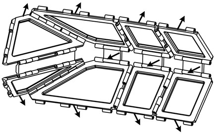
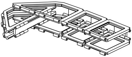
[0055] The present invention proposes a method for using a parabolic cylindrical expandable mechanism; the parabolic cylindrical expandable mechanism is composed of several expandable units; the using method includes a folding method and an unfolding method.

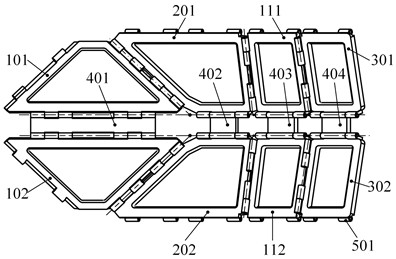
[0056] As shown in the figure, the expandable unit has a symmetrical structure up and down, consisting of a first isosceles trapezoid 101, a second isosceles trapezoid 102, a first right-angle trapezoid 201, a second right-angle trapezoid 202, and a third isosceles trapezoid. The trapezoid 111, the fourth isosceles trapezoid 112, the first rectangle 301, the second rectangle 302, the first hinge 401, the second hinge 402, the third hinge 403 and the fourth hinge 404; wherein, the first An isosceles trapezoid 101, the second isosceles trapezoid 102, the first right-angle trapezoid 201, the second right-angle trapezoid 202, the third isosceles trapezoid 111, the fourth etc. The waist trapezoidal piece 112 , the first recta...


PUM


Abstract

The invention discloses a using method of a parabolic cylinder deployable mechanism. The parabolic cylinder deployable mechanism is formed by combining a plurality of deployable units. Each deployable unit comprises a first isosceles trapezoid piece, a second isosceles trapezoid piece, a first right trapezoid piece, a second right trapezoid piece, a third isosceles trapezoid piece, a fourth isosceles trapezoid piece, a first rectangular piece, a second rectangular piece, a first hinge, a second hinge, a third hinge and a fourth hinge. The two deployable units form the one-layer parabolic cylinder deployable mechanism in a manner of sharing components, and the shared components comprise the first isosceles trapezoid piece and the second isosceles trapezoid piece; a plurality of parabolic cylinder deployable mechanisms with the layer number of 1 are sequentially connected through a fifth hinge to obtain the parabolic cylinder deployable mechanism; and the using method comprises a folding method and an unfolding method.

Description

technical field [0001] The invention relates to the field of expandable mechanisms, in particular to a method for using a parabolic cylinder expandable mechanism. Background technique [0002] The expandable mechanism first appeared in the 1960s as a new type of space structure, which can be unfolded when in use and folded when not in use. In the folded state, the structure is gathered in a certain shape, and under the action of external driving force, the structure is gradually unfolded, reaching the fully unfolded working state, and then locked into a stable state. In recent years, deployable mechanisms have been used in various engineering fields, from umbrellas and retractable roofs to space station deployable antennas and spacecraft solar panels. The expandable mechanism usually adopts a modular design, that is, the mechanism can be obtained through an array of expandable modules, and this expandable module is called an expandable unit. [0003] There are two main typ...

Claims


Application Information

Patent Timeline
Patent Type & Authority Applications(China)
IPC IPC(8): B64G1/22F16C11/04E04B7/16H01Q1/08A45B25/00
CPCB64G1/222F16C11/04E04B7/16H01Q1/084A45B25/00A45B2025/003
Inventor 范书豪曾鹏黄龙刘北胡锦鹏
Owner CHANGSHA UNIVERSITY OF SCIENCE AND TECHNOLOGY
Features
  • Generate Ideas
  • Intellectual Property
  • Life Sciences
  • Materials
  • Tech Scout
  • Unparalleled Data Quality
  • Higher Quality Content
  • 60% Fewer Hallucinations
Learn More