[0041] The technical solutions of the present invention will be described below in conjunction with the drawings, which is apparent from the accompanying drawings. Based on the embodiments of the present invention, all other embodiments obtained by those of ordinary skill in the art are in the range of the present invention without making creative labor premise.
[0042] In order to further illustrate the techniques taken from the present invention, the technical application examples will be described in detail below with reference to the preferred embodiments of the invention and their drawings.
[0043] In order to further understand the features and technical contents of the present invention, refer to the detailed description and description of the present invention, and the accompanying drawings provide only technical reference and description, which is not used to limit the present invention.
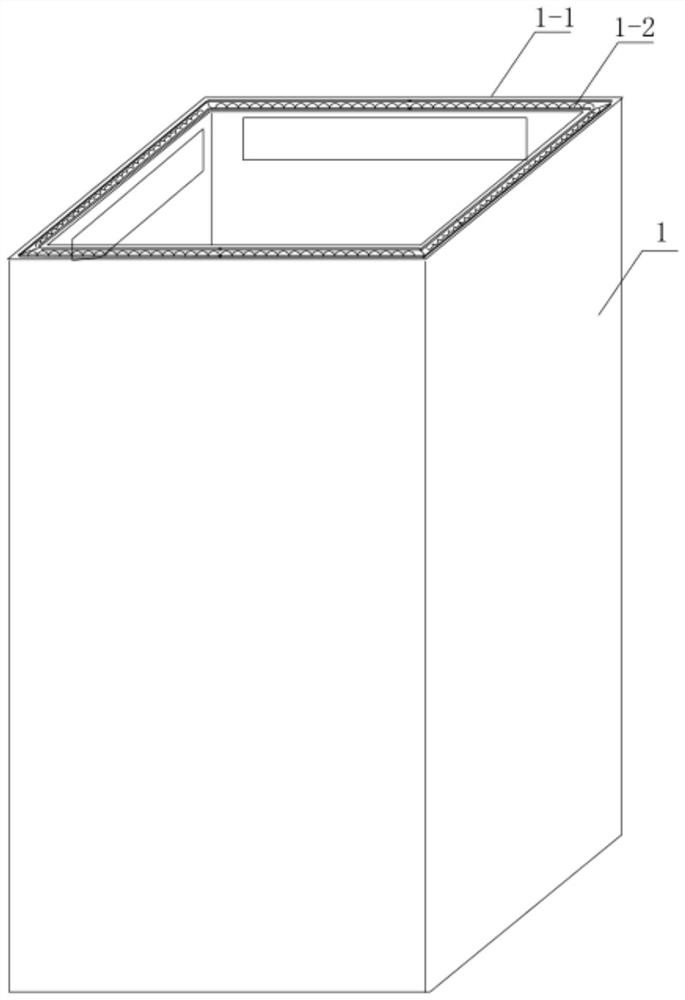
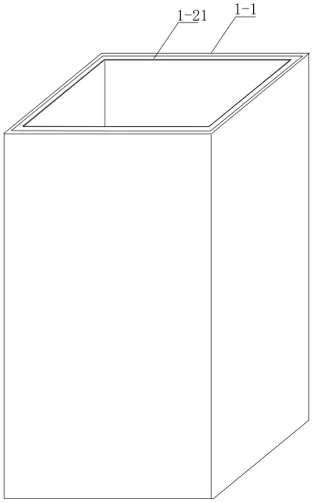
[0044] like figure 1 and figure 2 The species of the special box, including the box body 1 and the paper 1-1, the body of the cartridge 1-2 or the gray plate 1-21 is divided into four substrates by the V groove, four After the block substrate, the tubular, the upper and lower ends of the tubular, and the lower end are formed. Paper 15-1 covers the surface of the substrate and the substrate, the surface of the cartridge is surface paper.
[0045] exist figure 1 In the middle, the cartridge body 1, the lower end portion, the end of the ends of the face paper 1-1 and the ends of the corrugated plates 1-2, the pothsticks of the ends of the corrugated plates 1-2 are exposed, and the appearance is not beautiful.
[0046] exist figure 2 In the middle, the cartridge body 1, the lower end portion is composed of the ends of the surface paper 1-1 and the ends of the gray plates 1-21, and the ends of the gray plates 1-21 are exposed, and the appearance is not beautiful.
[0047] Further, in the end of the cartridge 1, glue, the glue can be hot melt glue, aqueous glue, plastic oil, and the like. The color of the glue is preferably colored from the surface paper 1-1 colors of the outer surface of the box body 1.
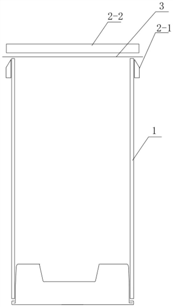
[0048] exist image 3 In the cover plate 3 cover the cartridge body 1 opening, the cover plate 3 simultaneously covers the end portion of the cartridge body, coupled to the end portion of the cartridge.
[0049] The cover 3 also includes an extension portion 3-1, and the extension 3-1 is integrated with the cover plate 3, which is a natural extension of the cover material. This is arranged, the cover 3 does not need to be accurately positioned when the opening is covered, and the tubular box is easily deformed and cannot be accurately positioned.
[0050] like image 3 , Figure 4 and Figure 7 The processed equipment of the special box body, including the first module 2-1 and the second module 2-2, and the first mold 2-1 is disposed on both sides of the box body 1, and the second mold 2-2 is provided in the cover. On the plate 3.
[0051] Figure 4In the middle, the second mold 2-2 is lowered to bond the cover 3 and the cartridge body 1 end portion, preferably in the bonding method, and heat-weld or plastic oil, the second mold 2-2, and the second mold 2-2. Set the high-cycle die or the heating portion 7, pressurized by pressurizing, hot melt glue or blistering oil by pressurizing, hot melt glue or blistering oil by pressurizing, hot melt glue or blistering oil by pressurizing, hot melt glue or blistering oil, bonding At the same time, the first mold 2-1 is moved upward, and the blade portion is separated by the blade portion of the first mold 2-1, so that the cover 2-1 is separated from the extension 3-1, the box When the body 1 is a quadrilateral, the first mold 2-1 can be two groups, or a set of molds, mold with angle. The hexagonal box is set to three groups of first molds 2-1. Two groups or three sets of first molds 2-1 can be designs sequentially, or after splicing.
[0052] The above is moved by the first mold 2-1, and the first mold 2-1 and the cover 3 can also be modeled by the cartridge 1.
[0053] The second mold 2-2 can also be self-with a blade, and the second mold 2-2 is pressed by the upper portion of the cover 3 and the cartridge body 1 by high permethum or electric heating, while cutting the cover 3, at this time A mold 2-1 can be positioned with a lower portion of the cover 3 and support the blade die of the second mold 2-2, so that the box body 1 is stabilized, which is advantageous for the second mold 2-2 to do accurate die cut.
[0054] exist Figure 5 In the middle, the cover plate 3 is provided between the upper portion of the box body 1, and the positioning member 5 is formed by the blister shape made of blister, the positioning portion of the central portion of the positioning member 5, the positioning portion positioning the bottle, the positioning parts 5 Part of the material extends into the box and is bonded to the inner wall of the box. The specific bonding method is preferably used to rotate the binder 1 four wall (tetra-shaped box) in the case of a rotating sprayer. The positioning member 5 is then entered, and the positioning member 5 and the inner wall of the cartridge body 1 are adhesived. Spray glue preferably hot melt adhesive, such as a PUR hot melt.
[0055] exist Figure 5 In the middle, the cover 3 and the positioning member 5 have a buffer member 6, and the buffer 6 mainly acts that the support cover 3 is removed from the top of the pressure.
[0056] exist Figure 5 In the middle, the extension portion 3-1 of the cover plate 3 is cut by the edge of the positioning member 5, and after heating, it is secured to the end portion of the cartridge body 1 after heating.
[0057] Image 6 In the middle, the extension 3-1 of the cover 3 is cut by the blade die, the edge is flush with the side panel of the box body 1, so that the appearance is basically the same as the ordinary manual boutique cartridge.
[0058] Figure 7 In the middle, the cartridge 1 is composed of paper paper 1-1 and corrugated plates 1-2, and the surface of the cartridge 1-1, the inner wall is corrugated 1-2.
[0059] The cover plate 3 covers two of the cartridge 1 end, the first mold 2-1 and the second mold 2-2 contact, and the extension 3-1 of the cover plate 3 is set by the first mold 2-1. The blade is cut and separated from the cover 3.
[0060] The first mold 2-1 is a mold cutting plate 3 by moving up, and the second mold 2-2 has a high-perimeted die or the heating portion 7, and the cover is made through a high-perimeted die portion 7 or a heating portion. 3 Adhesive with the body 1 end.
[0061] The inner wall of the cover 3 needs to be able to facilitate bonding oil, film, hot melt glue, and the like.
[0062] The cover 3 can be bonded directly to the end of the cartridge body 1 or bonded by an auxiliary member. For example, bonding with the bodies of the cartridge by a positioning member or the like.
[0063] As described above, various corresponding variations and deformations can be made in accordance with the technical solutions and technological concepts of the present invention, and all of these adjustments, changes, and deformation should belong to the claims of the present invention. protected range.