
Fresh air ventilator capable of reversing airflow and reversing method

A new fan and airflow technology, applied in the direction of using air flow as shielding, ventilation system, heating method, etc., can solve the problems of multi-power, large power consumption of fresh fan, energy waste, etc., to ensure reasonable use, improve service life, Energy saving effect

Pending Publication Date: 2022-02-01
SUZHOU GLANCETECH PHOTOELECTRIC SCI & TECH CO LTD
View PDF15 Cites 3 Cited by
  • Summary
  • Abstract
  • Description
  • Claims
  • Application Information

AI Technical Summary

Problems solved by technology

[0003] However, when the airflow passes through the heat exchanger, the fan often needs to output a large power consumption to ensure that the airflow passes through the heat exchanger smoothly. Therefore, during heat exchange, the power consumption of the new fan is relatively large.
And because generally in winter and summer, when the indoor and outdoor temperature difference is large, the heat exchanger has a high heat exchange recovery rate. In spring and autumn, there is generally no indoor heating or cooling, and the indoor and outdoor temperature difference is small. At this time, the effect of the heat exchanger is low, but it needs to consume more electric energy, and the electric energy paid is not proportional to the heat exchange energy obtained, resulting in energy waste

Method used


Image

  • Fresh air ventilator capable of reversing airflow and reversing method
  • Fresh air ventilator capable of reversing airflow and reversing method
  • Fresh air ventilator capable of reversing airflow and reversing method

Examples


Embodiment Construction

[0026] In order to make the above objects, features and advantages of the present application more clearly understood, the specific embodiments of the present application will be described in detail below with reference to the accompanying drawings. It should be understood that the specific embodiments described here are only used to explain the present application, but not to limit the present application. In addition, it should be noted that, for the convenience of description, only some structures related to the present application are shown in the drawings but not all structures. Based on the embodiments in this application, all other embodiments obtained by persons of ordinary skill in the art without making creative efforts belong to the scope of protection of this application.

[0027] The terms "comprising" and "having" and any variations thereof in this application are intended to cover a non-exclusive inclusion. For example, a process, method, system, product or dev...


PUM


Abstract

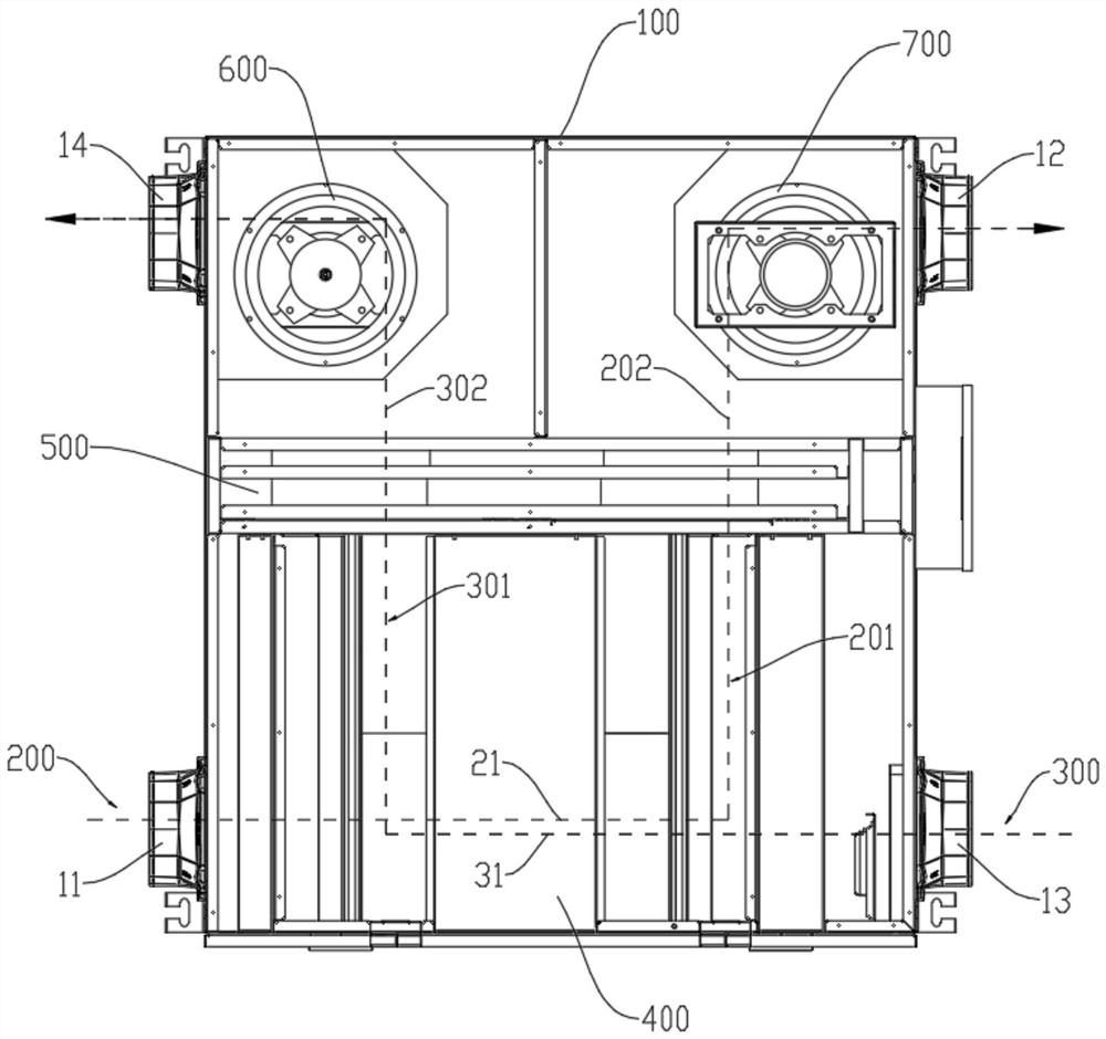
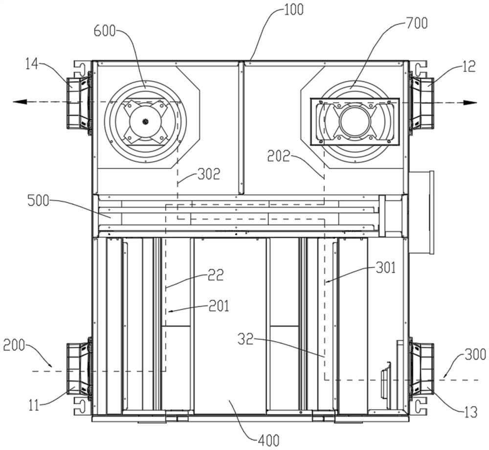
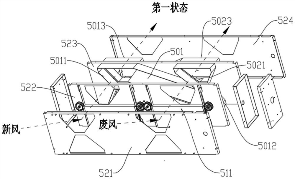
The invention discloses a fresh air ventilator capable of reversing airflow and a reversing method. The fresh air ventilator comprises: a machine shell provided with an air exhaust channel and a fresh air channel, a first air exhaust branch and a second air exhaust branch are formed in the air exhaust channel, and a first fresh air branch and a second fresh air branch are formed in the fresh air channel; a heat exchanger which is arranged in the machine shell, wherein the heat exchanger is connected to the first exhaust branch and the first fresh air branch so as to conduct heat exchange on the waste air and the fresh air; and a reversing valve which is arranged on the air exhaust channel and the fresh air channel, wherein the reversing valve can be switched to a first state or a second state, and responds to state switching to conduct the first air exhaust branch and the first fresh air branch and cut off the second air exhaust branch and the second fresh air branch, or cut off the first air exhaust branch and the first fresh air branch and conduct the second exhaust branch and the second fresh air branch. The waste air and the fresh air can flow through or not flow through the heat exchanger according to needs, reasonable use is guaranteed, the service life is prolonged, and energy consumption of the suction ventilator is reduced.

Description

technical field [0001] The invention relates to the technical field of fresh air blowers, in particular to a fresh air blower with reversible air flow and a reversing method. Background technique [0002] The fresh air fan is an effective air purification equipment. It can circulate the indoor and outdoor air by setting the exhaust channel and the fresh air channel. Introduced into the room through the fresh air channel. In the prior art, in order to make the temperature of the incoming fresh air tend to be indoors, heat exchangers are usually arranged on the exhaust air channel and the fresh air channel, so that the exhaust air and the fresh air can exchange heat in the heat exchanger. [0003] However, when the airflow passes through the heat exchanger, the fan often needs to output a large power consumption to ensure that the airflow passes through the heat exchanger smoothly. Therefore, the power consumption of the new fan is relatively large during heat exchange. And ...

Claims


Application Information

Patent Timeline
Patent Type & Authority Applications(China)
IPC IPC(8): F24F7/08F24F11/72F24F12/00F24F13/30
CPCF24F7/08F24F11/72F24F12/001F24F13/30
Inventor 毛凯吴健林佳源余辉
Owner SUZHOU GLANCETECH PHOTOELECTRIC SCI & TECH CO LTD
Learn More