Claw ratchet disc type stepping motor
A stepping motor and disc technology, applied in the direction of electrical components, electromechanical devices, electric components, etc., can solve the problems of slow signal response speed, low motor working efficiency, large rotor inertia, etc., to improve the working efficiency of the motor and reduce the inertia , Improve the effect of signal response speed
- Summary
- Abstract
- Description
- Claims
- Application Information
AI Technical Summary
Problems solved by technology
Method used
Image

Examples
Embodiment Construction
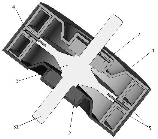
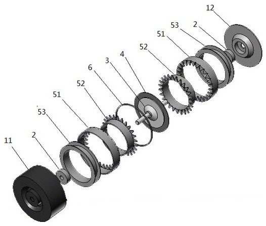
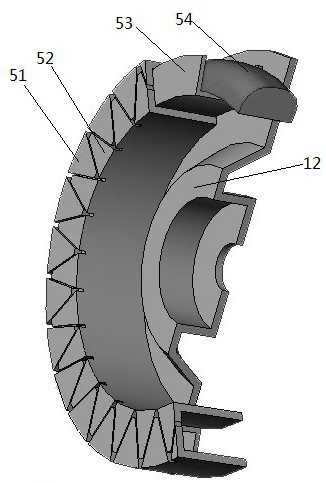
[0020] Such as Figure 1-3 As shown, a claw ratchet disc stepping motor includes a housing 1, and the two ends of the housing 1 are respectively connected to the shaft rods 31 on both sides of the rotor 3 through bearings 2; the outer periphery of the rotor 3 is a disc magnetic steel 4. Both sides of the rotor 3 are provided with pole plate assemblies 5, and each of the pole plate assemblies 5 is provided with a pawl structure on the end face facing the disc magnet 4, and each of the pole plate assemblies 5 is internally set There is a skeleton 53, a coil 54 is wound on the skeleton 53, a positioning ring 6 is arranged on the outer peripheral side of the disc magnet 4 and between the two pole plate assemblies 5, and the positioning ring 6 is used to separate two groups Pole plate combination 5, reserves the space that disk type magnetic steel 4 rotates. The two coils 54 are set to be energized at the same time, and the direction of the current is alternately changed.
[0021...
PUM
 Abstract
Description
Claims
Application Information
 - Generate Ideas
- Intellectual Property
- Life Sciences
- Materials
- Tech Scout
- Unparalleled Data Quality
- Higher Quality Content
- 60% Fewer Hallucinations
Browse by: Latest US Patents, China's latest patents, Technical Efficacy Thesaurus, Application Domain, Technology Topic, Popular Technical Reports.
© 2025 PatSnap. All rights reserved.Legal|Privacy policy|Modern Slavery Act Transparency Statement|Sitemap|About US| Contact US: help@patsnap.com