
Metal pipeline bending device

A technology for metal pipes and bending devices, applied in the field of bending devices, can solve the problems of reducing the strength of metal pipes, thinning metal pipe walls, and lowering the upper limit of pipeline flow, and achieves the effect of avoiding the reduction of flow and the reduction of pipeline strength.

Inactive Publication Date: 2022-02-08
江苏永占管道科技有限公司
View PDF13 Cites 1 Cited by
  • Summary
  • Abstract
  • Description
  • Claims
  • Application Information

AI Technical Summary

Problems solved by technology

[0003] Metal pipes often do not add supports inside during the bending process, which will cause the cross-sectional profile of the bent pipe to change from a circle to an ellipse at the bend, which will cause the cross-section of the pipe to bend. The area shrinks, which leads to a decrease in the upper flow limit of the pipeline. For example, a bending device for metal pipeline processing with application number 201921758604.7, which completes the bending of metal pipelines by means of intermediate compression, but still has the above problems, and it is bending During the process, the grooved edge on the workbench has the problem of scratching the outer circle of the metal pipe, and its ends are fixed by the clamping mechanism, which will limit the axial movement of the metal pipe to be bent, and the hydraulic rod is in the process of stretching In this process, the metal tube will be stretched and the metal tube will become longer, which will cause the wall of the bent metal tube to become thinner, resulting in a decrease in the strength of the bent metal tube

Method used


Image

  • Metal pipeline bending device
  • Metal pipeline bending device
  • Metal pipeline bending device

Examples


Embodiment Construction

[0033] The following will clearly and completely describe the technical solutions in the embodiments of the present invention with reference to the accompanying drawings in the embodiments of the present invention. Obviously, the described embodiments are only some, not all, embodiments of the present invention.

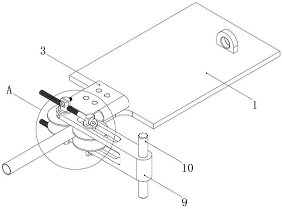
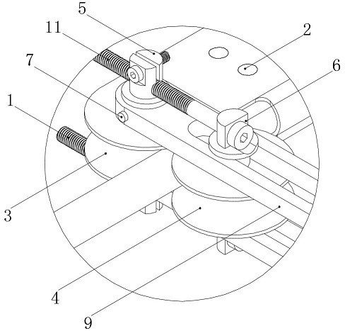
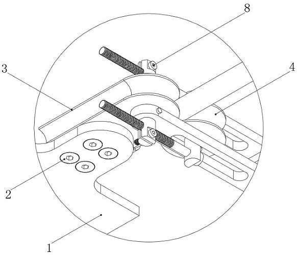
[0034] refer to Figure 1-Figure 12 , a metal pipe bending device, comprising an outer bending part, an inner support part and a winch, the outer bending part is located outside the metal pipe to be bent, and the inner support part is located inside the metal pipe to be bent;

[0035] refer to Figure 1-Figure 9 , the outer bending part includes a supporting plate 1 and a bending module 3 arranged above it, the winch is fixed above the supporting plate 1, the bending module 3 is rotatably connected with the pressing arm 9 through a vertical axis 5, and the pressing arm 9 has a built-in pressing wheel 4 and the second vertical axis 6, between the first vertical axis ...


PUM


Abstract

The invention discloses a metal pipeline bending device. The device comprises an outer bending part, an inner supporting part and a winch, the outer bending part is located on the outer side of a to-be-bent metal pipeline, the inner supporting part is located in the to-be-bent metal pipeline, the outer bending part comprises a supporting plate and a bending module arranged above the supporting plate, the bending module is rotationally connected with a pressing arm through a first vertical shaft, a pressing wheel and a second vertical shaft are arranged in the pressing arm, a pressing bolt is arranged between the first vertical shaft and the second vertical shaft, a module vertical shaft hole with the axis being in a vertical state is formed in the bending module, the edge of the bending module is provided with a module groove with the outline adapting to a metal pipeline to be bent and a module limiting part used for fixing the pipeline, a shaft threaded hole and a shaft end groove are formed in the two ends of the first vertical shaft, two outer circular truncated cones and two shaft through holes arranged at two ends of the vertical second shaft, the pressing arm comprises two arm forks, a sliding groove is formed in one end of each arm fork, and a fork vertical hole is formed in the other end of each arm fork. The metal pipeline bending device can avoid excessive deformation of the interior of a metal pipe during bending, and is suitable for being widely popularized and used.

Description

technical field [0001] The invention belongs to the technical field of bending devices, and in particular relates to a metal pipe bending device. Background technique [0002] Metal pipes are straight pipes after production and processing. In actual use, the metal pipes need to be bent to a certain extent according to the use requirements to meet the use requirements. [0003] Metal pipes often do not add supports inside during the bending process, which will cause the cross-sectional profile of the bent pipe to change from a circle to an ellipse at the bend, which will cause the cross-section of the pipe to bend. The area shrinks, which leads to a decrease in the upper flow limit of the pipeline. For example, a bending device for metal pipeline processing with application number 201921758604.7, which completes the bending of metal pipelines by means of intermediate compression, but still has the above problems, and it is bending During the process, the grooved edge on the ...

Claims


Application Information

Patent Timeline
Patent Type & Authority Applications(China)
IPC IPC(8): B21D9/07B21D9/03B21D9/16
CPCB21D9/073B21D9/03B21D9/16
Inventor 陆继江秦健朱顺平潘耀强
Owner 江苏永占管道科技有限公司
Learn More