Waterflow distribution variable fryer
a variable-flow, fryer technology, applied in the field of variable-flow distribution fryers, can solve the problems of deteriorating oil, fryers cannot efficiently promote the sinking of fried scum bits, etc., and achieve the effect of preventing the reduction of reducing the flow rate of water, and efficient acceleration
- Summary
- Abstract
- Description
- Claims
- Application Information
AI Technical Summary
Benefits of technology
Problems solved by technology
Method used
Image
Examples
first embodiment
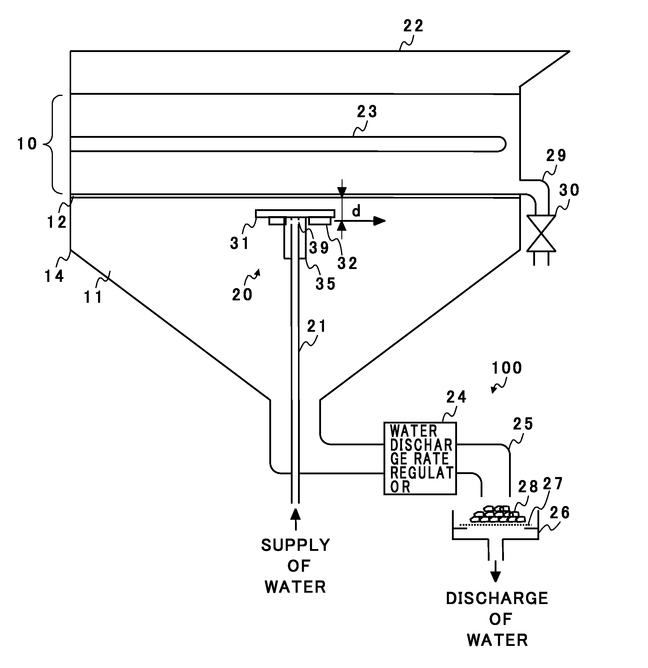
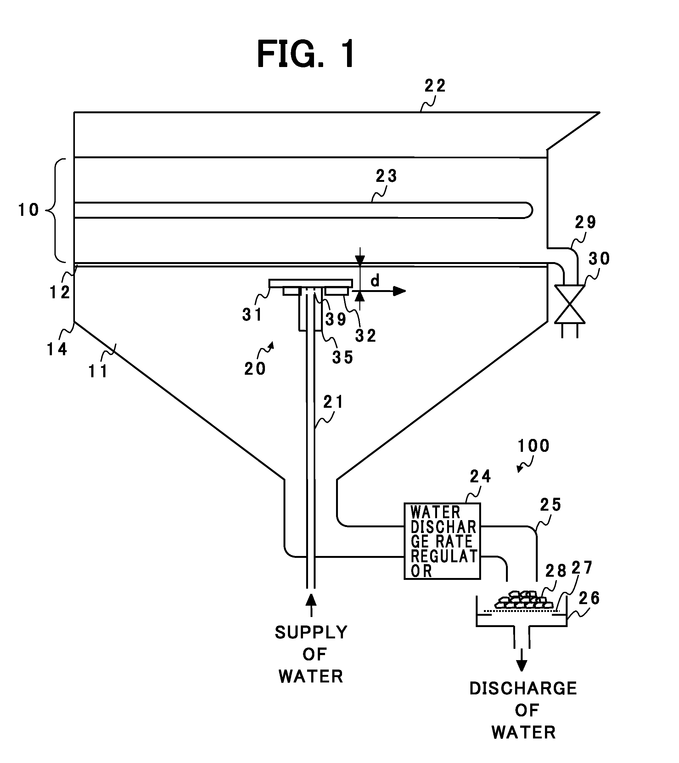
[0058]FIG. 1 is a schematic longitudinal sectional view of a variable waterflow-distribution fryer according to a first embodiment of the present invention.
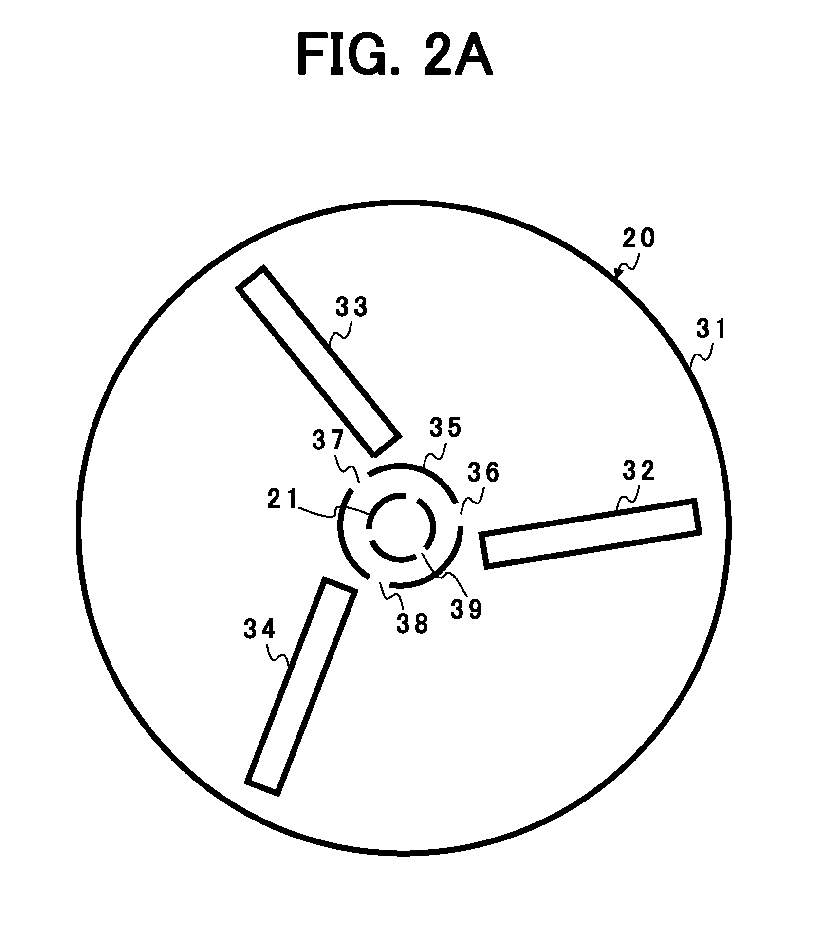
[0059]A tank 14 has a rectangular cross-section. The tank 14 includes an upper part having a hollow quadrangular prism shape and a lower part having a hollow, substantially reversed quadrangular pyramid shape. In the tank 14 are formed an oil layer 10 and a water layer 11, as will be described below. A water pipe 21 of a water supplier 20 is fixed to a lower-end center of the tank 14. The water pipe 21 extends vertically to pass through the center of the tank 14. Details of the structure of the water supplier 20 will be described later.
[0060]In the oil layer 10, a heater 23 is horizontally provided at a position of a half of a height direction size thereof.
[0061]A lower-end portion of the tank 14 is connected to a water discharger 100. The water discharger 100 includes a water discharge rate regulator 24 coupled to the lower-end ...
second embodiment
[0088]FIG. 6 is a schematic front view of a water supplier 20A of a variable waterflow-distribution fryer according to a second embodiment of the present invention.
[0089]The water supplier 20A includes a semi-circular plate 31A and a semi-circular plate 31B instead of the circular plate 31 shown in FIGS. 2A to 2C. The semi-circular plates 31A and 31B have a shape formed by splitting the circular plate 31 into halves. The semi-circular plate 31A is fixed to the upper end of the rotating pipe 35. The semi-circular plate 31A is positioned at the same height as that of the circular plate 31 of FIGS. 2A to 2C. In addition, the semi-circular plate 31B is fixed to the rotating pipe 35 at a position lower than a hole 38. The two blade plates 33 and 34 are fixed to a lower surface of the semi-circular plate 31A. The blade plate 32 is fixed to an upper surface of the semi-circular plate 31B. The arrangement of the respective blade plates 32 to 34 is the same as the arrangement of the respecti...
third embodiment
[0092]FIG. 7 is a schematic exploded perspective view of a water supplier 20B of a variable waterflow-distribution fryer according to a third embodiment of the present invention. FIG. 8 is a schematic front view of an assembly of the water supplier 20B shown in FIG. 7. FIG. 9 is a bottom view for illustrating an operation of the water supplier 20B shown in FIG. 8.
[0093]The water supplier 20B includes a circular plate 31C provided on an upper-end portion thereof. On the circular plate 31C are arranged three blade plates 32 to 34, as in the first embodiment above. Each of the blade plates 32 to 34 is fixed to the circular plate 31C in such a state that one surface thereof is inclined by substantially 45 degrees with respect to a vertical surface passing through the center portion of the circular plate 31C.
[0094]A hole is formed at the center portion of the circular plate 31C. A tip portion of a vertically extending spindle 50 is inserted into the hole. A stopper 51 and a stopper 52 ar...
PUM
 Abstract
Description
Claims
Application Information
 - R&D
- Intellectual Property
- Life Sciences
- Materials
- Tech Scout
- Unparalleled Data Quality
- Higher Quality Content
- 60% Fewer Hallucinations
Browse by: Latest US Patents, China's latest patents, Technical Efficacy Thesaurus, Application Domain, Technology Topic, Popular Technical Reports.
© 2025 PatSnap. All rights reserved.Legal|Privacy policy|Modern Slavery Act Transparency Statement|Sitemap|About US| Contact US: help@patsnap.com


