
Thermal shrinkage method of optical fiber thermal shrinkage protective sleeve

A protective sleeve, heat shrinking technology, applied in the direction of light guide, optics, optical components, etc., can solve the problems of uneven preheating shrinkage, inconsistent extension length, incomplete heating, etc. in the packaging process, so as to avoid adverse consequences and avoid extension length. Inconsistency, the effect of reducing microbending loss

Pending Publication Date: 2022-02-08
SHANGHAI TECHN INST OF ELECTRONICS & INFORMATION
View PDF0 Cites 0 Cited by
  • Summary
  • Abstract
  • Description
  • Claims
  • Application Information

AI Technical Summary

Problems solved by technology

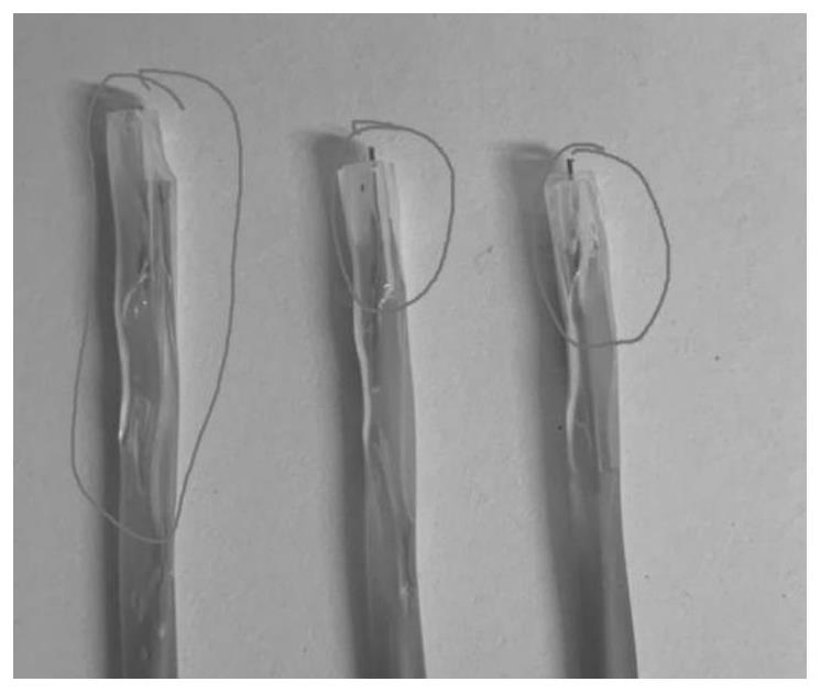
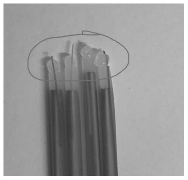
[0002] Due to the uneven manufacturing process of the traditional optical fiber heat shrinkable tube, the packaging process at both ends of the heat shrinkable tube has uneven preheating shrinkage on both sides, and the position of the reinforcing core in the middle also swings from side to side and is not centered. Different parts of the production process are poor. Due to insufficient heat shrinkage at both ends, the fiber heat shrinkable sleeve will still appear closed during use (excessive preheating shrinkage causes one side to be blocked and cannot be used), and opening (too small preheating shrinkage causes the inside Reinforcement core and inner layer heat shrinkable tube fall out, etc.) Due to the above reasons, the traditional fiber heat shrinkable sleeve with heat shrinkage at both ends will have the following problems during construction: (1) The heating plate of the heating tank has an intermediate reinforcing core Blocking, resulting in incomplete heating at both ends; (2) Excessive shrinkage of the internal heat shrink tube due to the lack of support at both ends, resulting in microbending of the optical fiber; (3) Heat caused by the unfixed position of the strengthening core After shrinking, the extension lengths of the two ends are inconsistent, and it is easy to cause breakage when it is inserted into the card slot; (4) due to the length of the two ends of the heat shrinkable tube exceeding the reinforcing core, the heating is not in place and the bell mouth appears unevenly; (5) due to the appearance The softening and drawing deformation of the heat-shrinkable tube caused by repeated heating after the bell mouth cannot be used; (6) Due to the offset of the internal reinforcing core, one end is not fixed and naturally bent after cooling, resulting in excessive loss

Method used


Image

  • Thermal shrinkage method of optical fiber thermal shrinkage protective sleeve
  • Thermal shrinkage method of optical fiber thermal shrinkage protective sleeve
  • Thermal shrinkage method of optical fiber thermal shrinkage protective sleeve

Examples


Embodiment Construction

[0024] In order to make the technical means and effects realized by the present invention easy to understand, the present invention will be described in detail below in conjunction with the embodiments and accompanying drawings.

[0025]

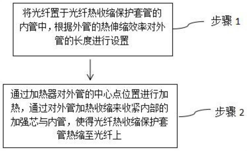
[0026] figure 1 It is a flow chart of a heat shrinking method for an optical fiber heat shrink protection sleeve in an embodiment of the present invention.

[0027] Such as figure 1 As shown, a thermal shrinkage method of an optical fiber heat shrinkable protective sleeve in this embodiment is used to heat shrink an optical fiber thermally shrinkable protective sleeve having an outer tube, a reinforcing core and an inner tube onto an optical fiber, comprising the following steps:

[0028] In step 1, the optical fiber is placed in the inner tube of the optical fiber heat-shrinkable protection sleeve, and the length of the outer tube is set according to the heat-shrinkable efficiency of the outer tube.

[0029] The outer tube is arranged o...


PUM


Abstract

The invention provides a thermal shrinkage method of an optical fiber thermal shrinkage protective sleeve, which is used for thermally shrinking the optical fiber thermal shrinkage protective sleeve with an outer tube, a reinforcing core and an inner tube onto an optical fiber, and comprises the following steps: 1, the optical fiber is placed in the inner tube of the optical fiber thermal shrinkage protective sleeve, and the length of the outer tube is set according to the thermal expansion efficiency of the outer tube; 2, the central point position of the outer tube is heated through a heater, the inner reinforcing core and the inner tube are tightened by heating and shrinking the outer tube, the optical fiber thermal shrinkage protection sleeve is made to be thermally shrunk to the optical fiber, the outer tube is arranged in the outer side of the inner tube, the reinforcing core is arranged between the inner tube and the outer tube, and the outer tube, the reinforcing core and the inner tube are consistent in length after thermal shrinkage.

Description

technical field [0001] The invention belongs to the field of optical fiber heat-shrinkable protection sleeves, and in particular relates to a heat-shrinking method for optical fiber heat-shrinkable protection sleeves. Background technique [0002] Due to the uneven manufacturing process of the traditional optical fiber heat shrinkable tube, the packaging process at both ends of the heat shrinkable tube has uneven preheating shrinkage on both sides, and the position of the reinforcing core in the middle also swings from side to side and is not centered. Different parts of the production process are poor. Due to insufficient heat shrinkage at both ends, the fiber heat shrinkable sleeve will still appear closed during use (excessive preheating shrinkage causes one side to be blocked and cannot be used), and opening (too small preheating shrinkage causes the inside Reinforcement core and inner layer heat shrinkable tube fall out, etc.) Due to the above reasons, the traditional f...

Claims


Application Information

Patent Timeline
IPC IPC(8): G02B6/44
CPCG02B6/44G02B6/443
Inventor 熊磊彭雪海李铭
Owner SHANGHAI TECHN INST OF ELECTRONICS & INFORMATION
Learn More