
Mobile communication antenna based on 5G communication

A communication antenna and mobile technology, which is applied to antenna combinations, antennas, antenna parts and other directions with different interactions, can solve problems such as limitations of installation and fixing methods, and achieve the effect of avoiding limitations and reducing space

Pending Publication Date: 2022-02-08
HENAN NORMAL UNIV
View PDF0 Cites 0 Cited by
  • Summary
  • Abstract
  • Description
  • Claims
  • Application Information

AI Technical Summary

Problems solved by technology

[0004] Aiming at the deficiencies of the existing technology, the present invention provides a mobile communication antenna based on 5G communication, which has the advantage of being conveniently fixed in different scenarios, and solves the problem that the current mobile antenna based on 5G communication needs to be used in different scenarios. , will be limited by the way it is installed and fixed

Method used


Image

  • Mobile communication antenna based on 5G communication
  • Mobile communication antenna based on 5G communication
  • Mobile communication antenna based on 5G communication

Examples


Embodiment 1

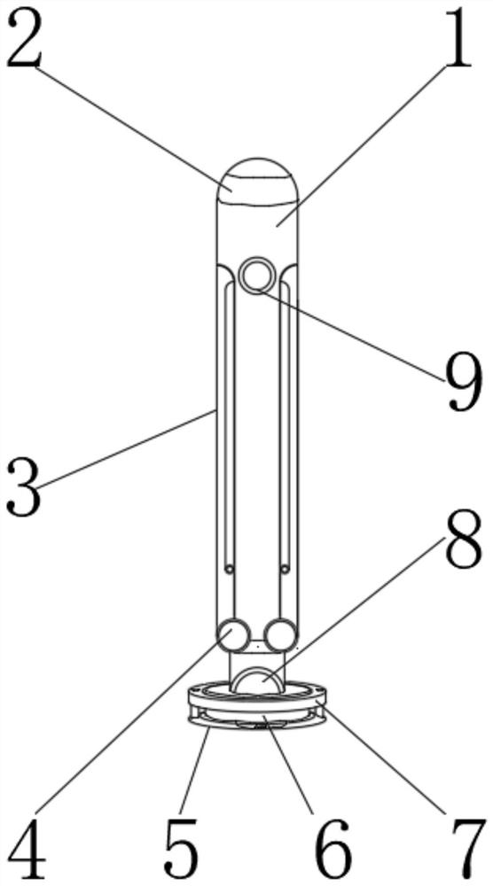
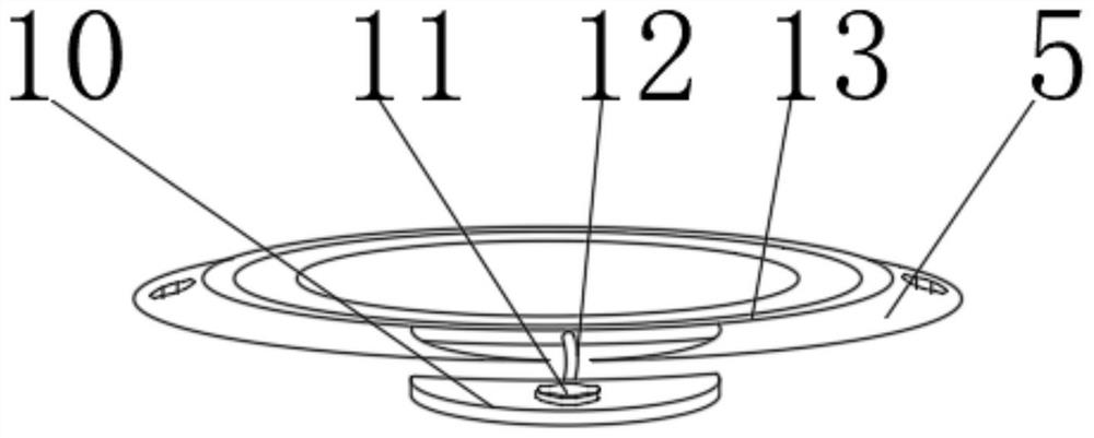
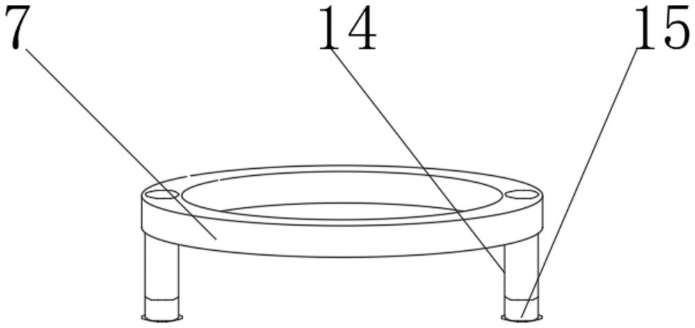
[0029] see Figure 1-4 , the present invention provides a mobile communication antenna based on 5G communication, including an antenna housing 1, the outer wall of the antenna housing 1 is rotatably connected with a first self-locking shaft 4, and the outer wall of the first self-locking shaft 4 is rotatably connected with a movable Column 3, the left inner surface of the movable column 3 is rotatably connected with a second self-locking shaft 18, the outer wall of the second self-locking shaft 18 is fixedly connected with a secondary antenna body 19, and the upper outer surface of the secondary antenna body 19 is slidably connected with a secondary antenna Housing 17, the outer surface of the lower end of the antenna housing 1 is fixedly connected with an adjustment shaft 8, the outer wall of the adjustment shaft 8 is rotatably connected with a connecting column 6, and the outer surface of the upper end of the connecting column 6 is movably connected with a reinforcing rib 14 ...

Embodiment 2

[0032] see figure 1 and Figure 5-6The outer wall of the antenna housing 1 is provided with a first self-locking shaft 4, the outer surface of the lower end of the movable column 3 is rotatably connected with the outer wall of the antenna housing 1 through the first self-locking shaft 4, and the outer surface of the lower end of the auxiliary antenna body 19 is passed through the first self-locking shaft 4. Two self-locking shafts 18 are rotationally connected with the left side inner surface of movable column 3, and the upper end outer surface of auxiliary antenna body 19 is provided with sliding groove, and the lower end inner surface of auxiliary antenna shell 17 passes through the upper end outer surface of auxiliary antenna body 19 Sliding connection, the inner surface of the upper end of the antenna housing 1 is provided with a sealing groove, the outer surface of the lower end of the antenna main body 2 is fixedly connected with the inner surface of the upper end of the...


PUM


Abstract

The invention belongs to the technical field of communication antennas, and discloses a mobile communication antenna based on 5G communication. The mobile communication antenna comprises an antenna shell, and the outer wall of the antenna shell is rotatably connected with a first self-locking shaft. According to the mobile communication antenna based on 5G communication, when a lower uneven surface needs to be fixed, a threaded column is mounted on the antenna in advance, then a threaded pipe mounted through reinforcing ribs below a limiting disc is aligned with the threaded column; the threaded column and the threaded pipe are locked after being aligned, so that the whole antenna is fixed conveniently; detachable discs are installed on the two sides of a suction cup through tension ribs; the detachable disc is pulled out through the tension ribs, an installation bolt on the detachable disc is aligned with a hidden buckle on the detachable disc on the other side so as to be connected with the hidden buckle, and meanwhile, the reinforcing ribs can be pulled out to be connected with the other set of reinforcing ribs, and the periphery can be fixed, and therefore, when the antenna is used in different scenes, various fixing modes can be carried out, and limitation is avoided.

Description

technical field [0001] The invention relates to the technical field of communication antennas, in particular to a mobile communication antenna based on 5G communication. Background technique [0002] The communication antenna is also called the antenna, and the antenna is a kind of converter, which converts the guided wave propagating on the transmission line into the electromagnetic wave propagating in the unbounded medium (usually free space), or performs the opposite transformation. A component used in radio equipment to transmit or receive electromagnetic waves. Engineering systems such as radio communication, broadcasting, television, radar, navigation, electronic countermeasures, remote sensing, and radio astronomy, which use electromagnetic waves to transmit information, rely on antennas to work. In addition, in terms of transmitting energy with electromagnetic waves, non-signal energy radiation also requires antennas. Generally, antennas are reversible, that is, th...

Claims


Application Information

Patent Timeline
Patent Type & Authority Applications(China)
IPC IPC(8): H01Q1/24H01Q1/12H01Q1/42H01Q1/00H01Q21/29
CPCH01Q1/24H01Q1/12H01Q1/42H01Q1/002H01Q21/29
Inventor 韩雪云马中军李肖松周应平
Owner HENAN NORMAL UNIV
Learn More