
Motion path planning method, device, equipment, medium and robotic arm of robotic arm

A technology of motion paths and robotic arms, applied in the field of robotic arms, can solve problems such as overflow and path points that cannot meet job requirements, and achieve the effect of expanding application scenarios

Active Publication Date: 2022-07-01
SHENZHEN YUEJIANG TECH CO LTD
View PDF6 Cites 0 Cited by
  • Summary
  • Abstract
  • Description
  • Claims
  • Application Information

AI Technical Summary

Problems solved by technology

[0003] However, due to the randomness of the sampling-based method, when the sampling space is the joint space of the manipulator, the generated path points cannot meet specific job requirements. For example, the manipulator needs to grab a glass of water and move to a given target point , it is necessary to ensure that the end posture of the robotic arm must be vertically upward during the entire movement process, otherwise the water in the cup will overflow during the movement process, so there are certain defects in the actual application process

Method used


Image

  • Motion path planning method, device, equipment, medium and robotic arm of robotic arm
  • Motion path planning method, device, equipment, medium and robotic arm of robotic arm
  • Motion path planning method, device, equipment, medium and robotic arm of robotic arm

Examples


Embodiment Construction

[0063] The following describes in detail the embodiments of the present invention, examples of which are illustrated in the accompanying drawings, wherein the same or similar reference numerals refer to the same or similar elements or elements having the same or similar functions throughout. The embodiments described below with reference to the accompanying drawings are exemplary, and are intended to be used to explain the present invention, but should not be construed as a limitation of the present invention. Based on the embodiments of the present invention, those of ordinary skill in the art will not make any creative work on the premise. All other embodiments obtained below belong to the protection scope of the present invention.

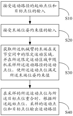
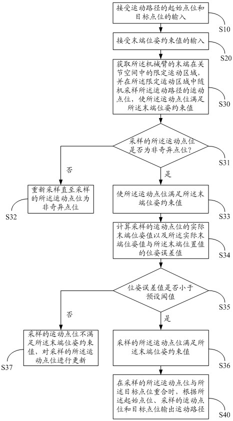
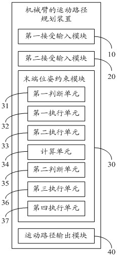
[0064] The present invention proposes a motion path planning method for a robotic arm, refer to figure 1 and figure 2 , the motion path planning method of the manipulator includes:

[0065] Step S10: accept the input of the starting point and...


PUM


Abstract

The invention discloses a motion path planning method for a mechanical arm. The motion path planning method for a mechanical arm comprises: accepting the input of the starting point and target point of the motion path; accepting the input of the end pose constraint value; obtaining the mechanical The limited motion area of ​​the end of the arm in the joint space, and the motion points of the motion path are randomly sampled in the limited motion area, so that the motion points satisfy the end pose constraint value; When the motion point coincides with the target point, the motion path is output according to the start point, the sampled motion point and the target point. The path points on the motion path planned and generated by the motion path planning method of the mechanical arm of the present invention can meet the given end pose requirements, realize specific operation requirements, and expand application scenarios.

Description

technical field [0001] The present invention relates to the technical field of robotic arms, in particular to a motion path planning method, device, equipment, medium and robotic arm of a robotic arm. Background technique [0002] As the basis for manipulators to complete various tasks, path planning has always been a research hotspot. At present, the existing path planning methods mostly use sampling-based methods, such as RRT (Rapidly-Exploring Random Trees) algorithm and PRM (Probabilistic Roamap Method, random roadmap) algorithm. [0003] However, due to the randomness of the sampling-based method, when the sampling space is the joint space of the robotic arm, the generated path points cannot meet specific job requirements. For example, the robotic arm needs to grab a glass of water and move to a given target point , then the robot arm needs to ensure that its end posture must be vertically upward during the entire movement process, otherwise the water in the cup will o...

Claims


Application Information

Patent Timeline
Patent Type & Authority Patents(China)
IPC IPC(8): B25J9/16B25J13/00
CPCB25J9/1664B25J9/161B25J13/00
Inventor 林炯辉郎需林黄睿刘主福刘培超
Owner SHENZHEN YUEJIANG TECH CO LTD
Learn More