Corpse incineration system

A corpse and cremator technology, applied in the field of corpse incineration systems, can solve the problems of inconvenience in cleaning the inner wall of the cremator

Pending Publication Date: 2022-02-11
HANGZHOU LIAO FA ENVIRONMENT EQUIP
View PDF0 Cites 0 Cited by
  • Summary
  • Abstract
  • Description
  • Claims
  • Application Information

AI Technical Summary

Problems solved by technology

[0004] After the cremation of the remains, the ashes will be removed from the cremation furnace and collected and returned to the family members. However, the smoke stains and residues produced during the cremation process will adhere to the inner wall of the cremation furnace. Due to the narrow space in the inner cavity of the cremation furnace, it is extremely inconvenient for the staff to clean the inner wall of the cremation furnace, so it needs to be improved

Method used


Image

  • Corpse incineration system
  • Corpse incineration system
  • Corpse incineration system

Examples


Embodiment Construction

[0042] The following is attached Figure 1-11 The application is described in further detail.

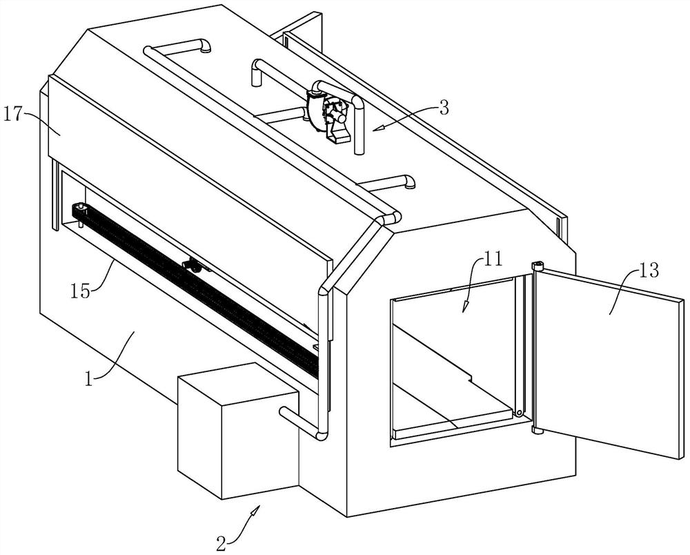
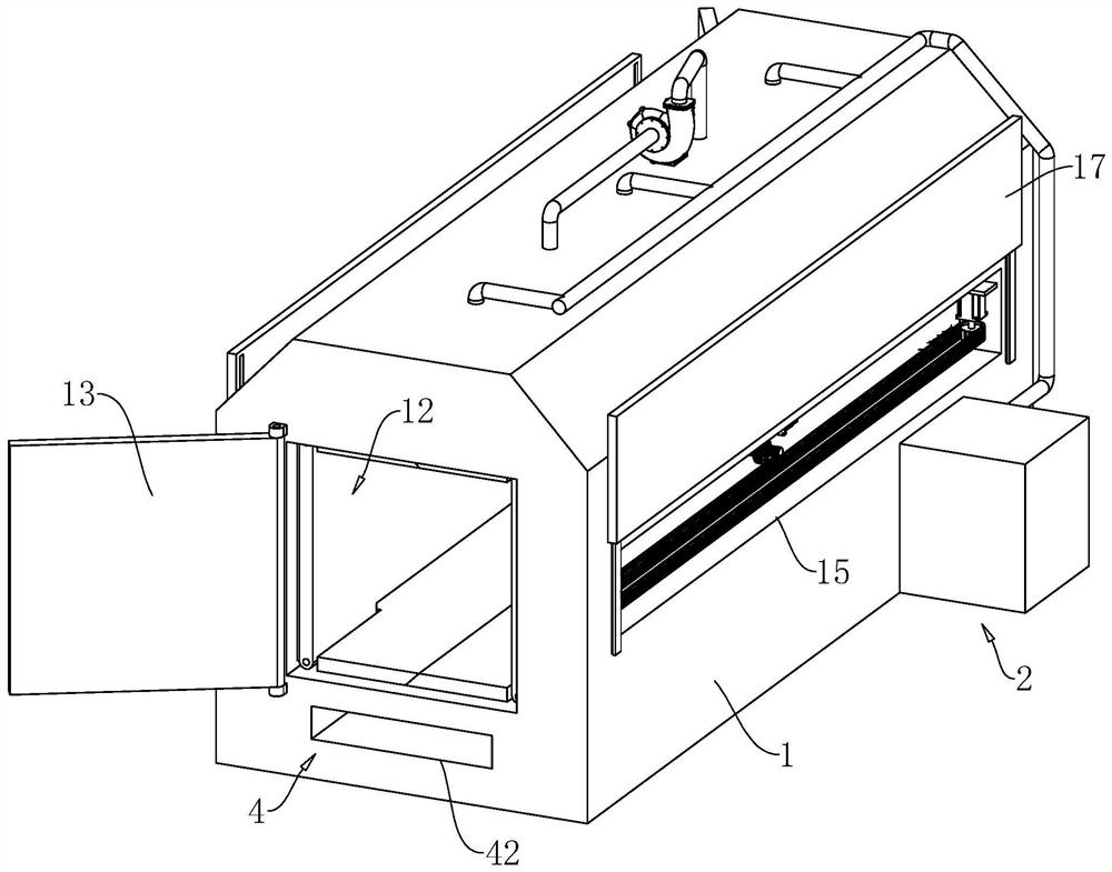
[0043] The embodiment of the present application discloses a corpse incineration system. refer to figure 1 with figure 2 , The incineration system includes a cremation furnace 1 , a combustion module 2 , an air supply module 3 and a smoke exhaust module 4 .

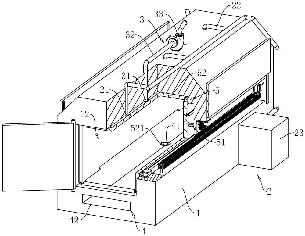
[0044] refer to figure 1 with image 3 One end of the cremation furnace 1 is provided with an entrance 11, and the body is sent into the cremation furnace 1 through the entrance 11. The combustion module 2 includes an oil tank 23 located on one side of the cremation furnace 1 for storing fuel oil. The inner top wall of the cremation furnace 1 is provided with a flame nozzle 21, and an oil pipe 22 is connected between the flame nozzle 21 and the oil tank 23. The fire head 21 is ejected and forms a flame to cremate the remains.

[0045] refer to image 3 , the air supply module 3 includes a blower 33 located on one side ...


PUM


Abstract

The invention belongs to the field of cremators and relates to a corpse incineration system. The system comprises a cremator. The system is characterized in that: baffles are arranged on the inner walls of one pair of two opposite sides in the cremator respectively; each baffle comprises a panel and two side plates connected to the two sides of the panel, wherein the two side plates are located on the side, close to the other panel, of the panel, each side plate abuts against the inner wall of the cremator on the same side, and the two side plates on the same side of the two panels abut against each other. the two baffles are arranged in the extending direction of an inner cavity of the cremator in a sliding mode, two driving assemblies corresponding to the two baffles are arranged on the outer side of the cremator, an inlet and a cleaning opening are formed in the two ends of the cremator respectively, and the driving assemblies are used for driving the corresponding baffles to enter and exit from the cremator through the cleaning opening. According to the corpse incineration system of the invention adopted, a worker can conveniently clean the inner cavity of the cremator.

Description

technical field [0001] The present application relates to the field of cremation furnaces, in particular to a corpse incineration system. Background technique [0002] The cremation furnace is the equipment used by the crematorium to cremate the remains, which belongs to a kind of incinerator. [0003] The cremation system currently used in the crematorium basically includes a cremation furnace, a combustion system, an air supply system and a flue gas treatment system. During the cremation process of the remains in the cremation furnace by the combustion system, the air supply system continuously sends the air required for combustion into the cremation furnace, and the smoke treatment system collects and filters the smoke generated by the cremation of the remains before discharging it. [0004] After the cremation of the remains, the ashes will be removed from the cremation furnace and collected and returned to the family members. However, the smoke stains and residues prod...

Claims


Application Information

Patent Timeline
IPC IPC(8): F23G1/00
CPCF23G1/00
Inventor 丁山王颖武国贵
Owner HANGZHOU LIAO FA ENVIRONMENT EQUIP
Why Eureka
Try Eureka