
Switch cabinet partial discharge positioning test method based on TEV and ultrahigh frequency method

A test method and partial discharge technology, applied in the direction of testing dielectric strength, etc., can solve problems such as difficult positioning, analysis of discharge source of switchgear, etc.

Pending Publication Date: 2022-02-11
MAINTENANCE CO STATE GRID QINGHAI ELECTRIC POWER +2
View PDF0 Cites 0 Cited by
  • Summary
  • Abstract
  • Description
  • Claims
  • Application Information

AI Technical Summary

Problems solved by technology

[0004] In order to overcome the shortcomings of the existing technology, the present invention proposes a detection method using an effective combination of TEV and UHF partial discharge detection technology, which solves the problem of difficult analysis and positioning of the discharge source inside the switchgear

Method used


Image

  • Switch cabinet partial discharge positioning test method based on TEV and ultrahigh frequency method
  • Switch cabinet partial discharge positioning test method based on TEV and ultrahigh frequency method
  • Switch cabinet partial discharge positioning test method based on TEV and ultrahigh frequency method

Examples


Embodiment 1

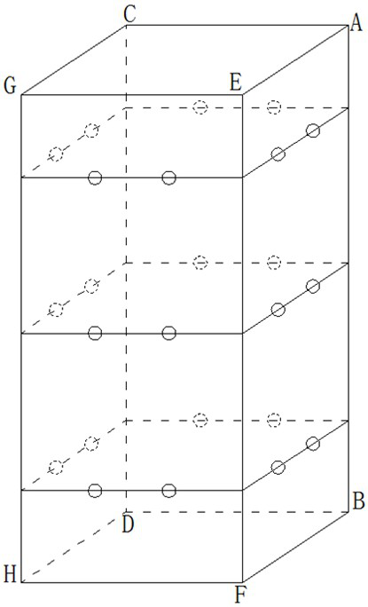
[0018] Embodiment 1, the present invention provides a switchgear partial discharge location test method based on TEV and UHF method, comprising the following steps:

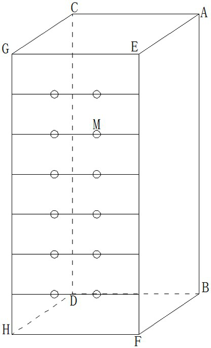
[0019] Step1, use the transient ground potential test method to conduct general testing on the front, side, and back of the switchgear panel, divide the cuboid of the switchgear into 3 layers, and select 2 point measuring points on each side and each layer. If abnormal signals are detected, filter On the surface with the largest signal, continue to use the transient ground potential test method for precise detection, that is, divide the surface into 6 layers, select 2 measuring points for each layer, and screen out the point with the largest transient ground potential signal amplitude on the surface M.

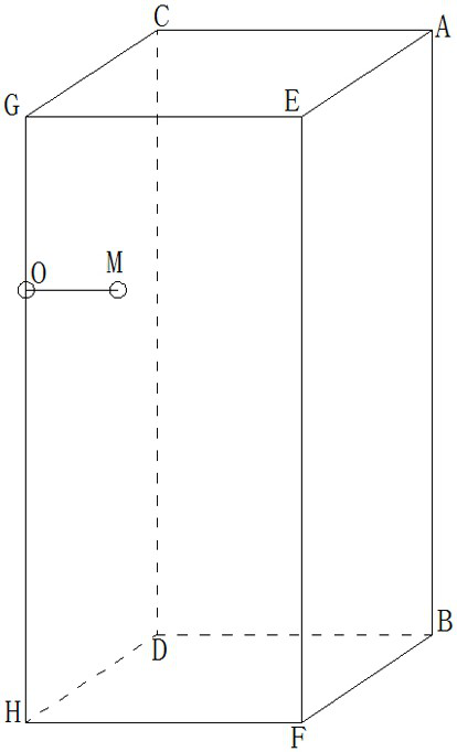
[0020] Step2, use an oscilloscope to perform UHF partial discharge detection, move the probe slowly along the gaps of AB, CD, EF and HG on the edge of the switch cabinet to detect the point O with the maximum amp...

Embodiment 2

[0028] Embodiment 2, the present invention provides a switchgear partial discharge location test method based on TEV and UHF method, comprising the following steps:

[0029] Step1, use the transient ground potential test method to conduct general testing on the front, side, and back of the switchgear panel, divide the cuboid of the switchgear into 3 layers, and select 2 point measuring points on each side and each layer. If abnormal signals are detected, filter On the surface with the largest signal, continue to use the transient ground potential test method for precise detection, that is, divide the surface into 6 layers, select 3 measuring points for each layer, and screen out the point with the largest transient ground potential signal amplitude on the surface M.

[0030] Step2, when the heights of O and M deviate and are not at the same height, select the average height of O and M, and draw a horizontal line NP at this height, which is the closest height line to the fault ...


PUM


Abstract

A switch cabinet partial discharge positioning test method based on a TEV and an ultrahigh frequency method relates to the technical field of power equipment partial discharge testing, and comprises the following steps: firstly, screening out the approximate height and position of the partial discharge of a switch cabinet by using a transient ground potential test method, and then determining the fault height by using an ultrahigh frequency partial discharge detection method; and determining the accurate position of the fault through an ultrahigh frequency partial discharge detection method. The beneficial effects of the invention are that the method achieves the combined analysis of the ultra-TEV and ultrahigh frequency partial discharge signals when the switch cabinet breaks down, forms an effective detection method for the multi-means and multi-angle analysis and positioning of the internal discharge of the switch cabinet, solves the problems of the analysis and positioning of the internal discharge source of the switch cabinet, and provides a thought and an effective solution for positioning of partial discharge sources of all switch cabinet equipment.

Description

technical field [0001] The invention relates to the technical field of partial discharge testing of power equipment, in particular to a method for locating and testing switch cabinet partial discharge based on TEV and UHF methods. Background technique [0002] Existing partial discharge detection technologies for power equipment include ultrasonic partial discharge detection, ultra-high frequency partial discharge detection, high frequency partial discharge detection, ultrasonic partial discharge detection and other technologies, but the above partial discharge detection technologies have their own limitations. The switchgear is One of the most important equipment in the substation, operation safety plays a decisive role in the reliability of power supply, and its condition is directly related to the safe and economical operation of the power system. Through the application of partial discharge detection technology, the early defects of switchgear can be found in time, laten...

Claims


Application Information

Patent Timeline
Patent Type & Authority Applications(China)
IPC IPC(8): G01R31/12
CPCG01R31/12
Inventor 马智明王元友王雅湉曾成杨博李洪涛丁祥浩马小林耿坤何海川张济麟刘伟强袁复晓伊国鑫王泰年马国福郭永钰韩思银任丽闪常杰金晓红
Owner MAINTENANCE CO STATE GRID QINGHAI ELECTRIC POWER
Learn More