
Scattering parameter test circuit and method suitable for long delay device

A device and test signal technology, which is applied in the direction of measuring electrical variables, measuring resistance/reactance/impedance, instruments, etc., can solve problems such as intermediate frequency signal errors, failure to obtain test signals, and inability to correspond data correctly, so as to avoid data errors, The effect of precise testing

Active Publication Date: 2017-08-11
THE 41ST INST OF CHINA ELECTRONICS TECH GRP
View PDF6 Cites 0 Cited by
  • Summary
  • Abstract
  • Description
  • Claims
  • Application Information

AI Technical Summary

Problems solved by technology

[0005] 1. Since the signal excitation, signal reception and analysis processing of the long-delay device tested by the traditional vector network analyzer is only through phase-locking to achieve synchronous scanning, there is a lack of timing synchronization measurement and control mechanism between each part. When the vector network analyzer tests scanning and analysis When there is a large difference between the time of the long-delay device and the inherent delay characteristics of the long-delay device, in the reference and test receiving unit of the vector network analyzer, the excitation signal and the test signal transmitted by the long-delay device will be caused by the phase-locked working mode Errors occur in the corresponding intermediate frequency signal generated by signal reception, and the test signal with correct delay characteristic information cannot be obtained
[0006] 2. Since the signal excitation, signal reception and analysis processing of long-delay devices tested by traditional vector network analyzers only realize synchronous scanning through phase-locking, data acquisition and analysis processing are also carried out in accordance with the phase-locking working mode. The data information lacks an identification and processing mechanism based on a unique mapping. When there is a big difference between the test scanning and analysis time of the vector network analyzer and the inherent delay characteristics of the long-delay device, neither the correct delay can be obtained. characteristic information of the test signal, and at the same time, it is impossible to correctly correspond to the data obtained by each frequency test signal, so it is even more impossible to obtain the test result with the correct delay characteristic information

Method used


Image

  • Scattering parameter test circuit and method suitable for long delay device

Examples


Embodiment 1

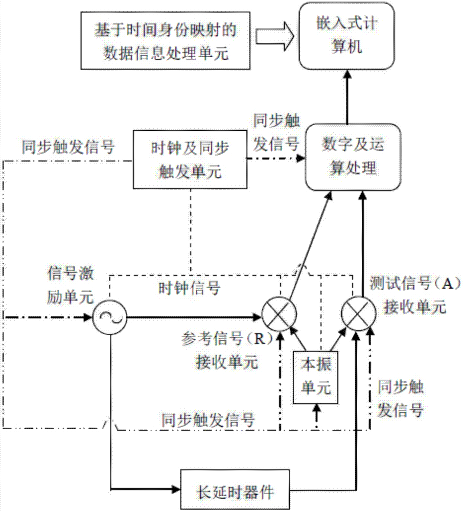
[0037] Such as figure 1 As shown, a scattering parameter test circuit suitable for long-delay devices includes a signal excitation unit, a local oscillator unit, a reference signal (R) receiving unit, a test signal (A) receiving unit, a digital and arithmetic processing unit, and an embedded Computer, clock and synchronous trigger unit and data information processing unit based on time identity mapping;

[0038] Under the control of the embedded computer, the excitation signal generated by the signal excitation unit is divided into two channels, one is input to the reference signal receiving unit, and the other is input to the measured long-delay device; the local oscillator signal generated by the local oscillator unit is divided into two One way is input to the reference signal receiving unit, and the other is input to the test signal receiving unit; the reference signal (R) receiving unit receives the excitation signal and the local oscillator signal, and generates a refere...

Embodiment 2

[0040] On the basis of the above embodiments, the present invention also mentions a method for accurately testing scattering parameters suitable for long-delay devices, which specifically includes the following steps:

[0041] Step 1: Obtain the information (amplitude / phase / time delay) of the reference signal R;

[0042] Under the control of the embedded computer, the reference signal receiving unit receives the excitation signal from the signal excitation unit and the local oscillation signal of the local oscillation unit, and generates the signal carrying the characteristic information of the excitation signal in a frequency conversion mode under the state of phase-locked synchronization and trigger control. Refer to the intermediate frequency signal, input the intermediate frequency signal to the digital and arithmetic processing unit for digital processing and reference information extraction, and obtain the characteristic information data accurately mapped with the referen...


PUM


Abstract

The invention discloses a scattering parameter test circuit and method suitable for a long delay device, and belongs to the technical field of microwave test. The test circuit and method can realize accurate test of delay characteristics of the long delay device under any test scanning and analysis condition no longer through an approximate test method attached by limitation conditions, for different actual test application requirements, can realize accurate test without pre-knowing magnitude range of inherent delay characteristics of the long delay device, solve the problem of accurate test and evaluation of the delay characteristics of the long delay device effectively, and maximally meet the actual application test requirements and higher technical requirements in a general manner.

Description

technical field [0001] The invention belongs to the technical field of microwave testing, and in particular relates to a scattering parameter testing circuit and method suitable for long-delay devices. Background technique [0002] With the rapid development and progress of related technologies in the fields of satellite navigation, wireless communication, and the Internet of Things, the technical system and composition state of long-delay devices are becoming increasingly complex, and higher requirements are placed on the technical characteristics of time delay. (That is, the accurate acquisition of corresponding transmission scattering parameters) also presents a more urgent demand, so newer and higher technical requirements are put forward for testing technology or related products. The test architecture and processing technology of traditional vector network analyzers can no longer meet the new test requirements, and it is necessary to innovate or form test methods and t...

Claims


Application Information

Patent Timeline
Patent Type & Authority Applications(China)
IPC IPC(8): G01R27/28
CPCG01R27/28
Inventor 郭敏王尊峰
Owner THE 41ST INST OF CHINA ELECTRONICS TECH GRP
Learn More