Self-locking support

A self-locking, the other side of the technology, applied in the field of sight, can solve the problem of difficult to fix the flip angle, unstable position of the lens barrel, cumbersome unlocking method, etc.

Pending Publication Date: 2022-02-11
ZHUHAI RUITE PHOTOELECTRIC TECH CO LTD
View PDF6 Cites 0 Cited by
  • Summary
  • Abstract
  • Description
  • Claims
  • Application Information

AI Technical Summary

Problems solved by technology

However, in the prior art, since the fixed seat and the mounting seat are connected by hinges, the relative position between the two is difficult to lock, and it is usually necessary to use additional fixing parts to ensure that the position of the lens barrel is fixed. At the same time, during the flipping process , the flip angle is difficult to fix, so it has disadvantages such as locking and unlocking methods are cumbersome and the position of the lens barrel is unstable

Method used


Image

  • Self-locking support
  • Self-locking support
  • Self-locking support

Examples


Embodiment Construction

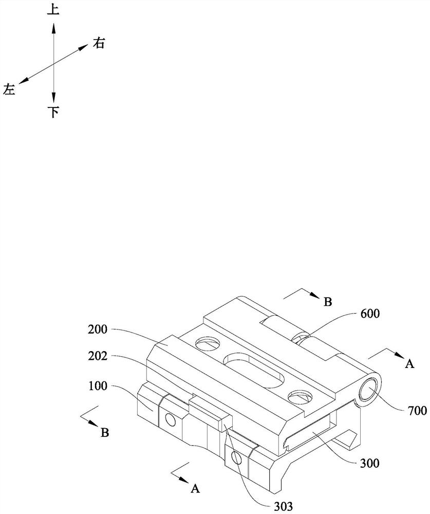
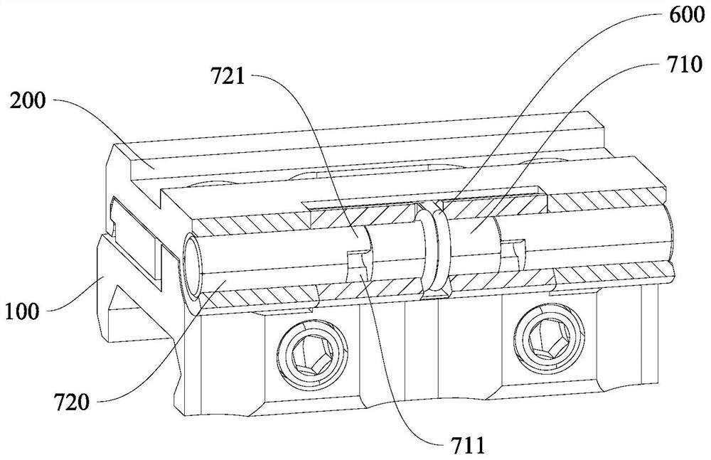
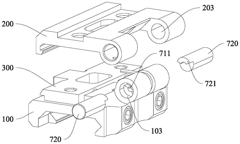
[0023] Embodiments of the present invention are described in detail below, and examples of the embodiments are shown in the drawings, wherein the same or similar reference numerals denote the same or similar elements or elements having the same or similar functions throughout. The embodiments described below by referring to the figures are exemplary only for explaining the present invention and should not be construed as limiting the present invention.

[0024] In describing the present invention, it is to be understood that the terms "upper", "lower", "front", "rear", "left", "right", "transverse", "longitudinal", "vertical" etc. The indicated orientation or positional relationship is based on the orientation or positional relationship shown in the drawings, and is only for the convenience of describing the present invention and simplifying the description, rather than indicating or implying that the referred device or element must have a specific orientation, or in a specific...


PUM


Abstract

The invention discloses a self-locking support which comprises a fixed seat. An overturning seat is rotatably connected with the fixed seat; a rotating shaft piece is connected with the overturning seat and the fixed seat and comprises a fixed shaft and a rotating shaft which are coaxially arranged, the fixed shaft is arranged on the fixed seat, the rotating shaft is arranged on the overturning seat, a first convex part is arranged at the end part of the fixed shaft, a second convex part is arranged on the rotating shaft towards the fixed shaft, the rotating shaft is suitable for rotating along with the overturning seat and enabling the first convex part and the second convex part to be in contact with each other or separated from each other; a push plate is arranged on the fixed seat in a sliding manner; and an elastic piece is connected with the push plate and the fixed seat, the elastic piece is suitable for driving the push plate to move towards the other side of the overturning seat and is connected with the overturning seat, and the push plate is suitable for fixing the overturning seat and the fixed seat. The fixing mode of the support is simple and fast, a tedious fixing and assembling structure is avoided, and the locking and overturning efficiency of a sighting telescope is greatly improved.

Description

technical field [0001] The invention relates to scope technology, in particular to a self-locking bracket. Background technique [0002] The overturn bracket is usually used for the assembly of the lens barrel, especially the magnifier. The overturn bracket in the magnifier usually includes a fixed seat and a mounting seat hinged to each other. The fixed seat is used to fix the bracket, and the mounting seat is used to install the lens barrel. The position of the lens barrel is adjusted based on the rotation of the fixed seat, and the locking state and flipping state of the flip seat on the bracket are adjusted to meet the use requirements of different environments. However, in the prior art, since the fixed seat and the mounting seat are connected by hinges, the relative position between the two is difficult to lock, and it is usually necessary to use additional fixing parts to ensure that the position of the lens barrel is fixed. At the same time, during the flipping proce...

Claims


Application Information

Patent Timeline
Patent Type & Authority Applications(China)
IPC IPC(8): G02B23/16
CPCG02B23/16
Inventor 高瑞程娟胡运波
Owner ZHUHAI RUITE PHOTOELECTRIC TECH CO LTD
Why Eureka
Try Eureka