Automatic heat dissipation protection device for transformer

A technology for protection devices and transformers, which is applied in the field of transformers, can solve problems such as transformer shaking, dumping, and inability to dissipate heat in time, and achieve the effect of reducing shaking amplitude and avoiding damage

Inactive Publication Date: 2022-02-11
杨齐全
View PDF0 Cites 2 Cited by
  • Summary
  • Abstract
  • Description
  • Claims
  • Application Information

AI Technical Summary

Problems solved by technology

[0003] Existing transformers usually only simply dissipate heat through the cooling vents. Usually, the transformer will not be damaged due to overheating, but sometimes the transformer will be overloaded, and the heat generated at this time will be more. Only through the cooling vents can not be dissipated in time. Overload will lead to overheating and damage to the transformer, and the heat dissipation port is usually equipped with a filter screen to place dust in. If the time is too long, debris or dust will adhere to the filter screen port, which will affect the ventilation and affect the heat dissipation effect. For outdoor setting, in windy weather, the casing with the transformer shakes too much, causing the transformer to shake or even fall over, causing damage to the transformer or even other accidents, and the safety is low

Method used


Image

  • Automatic heat dissipation protection device for transformer
  • Automatic heat dissipation protection device for transformer
  • Automatic heat dissipation protection device for transformer

Examples


Embodiment Construction

[0024] The following will clearly and completely describe the technical solutions in the embodiments of the present invention with reference to the accompanying drawings in the embodiments of the present invention. Obviously, the described embodiments are only some, not all, embodiments of the present invention.

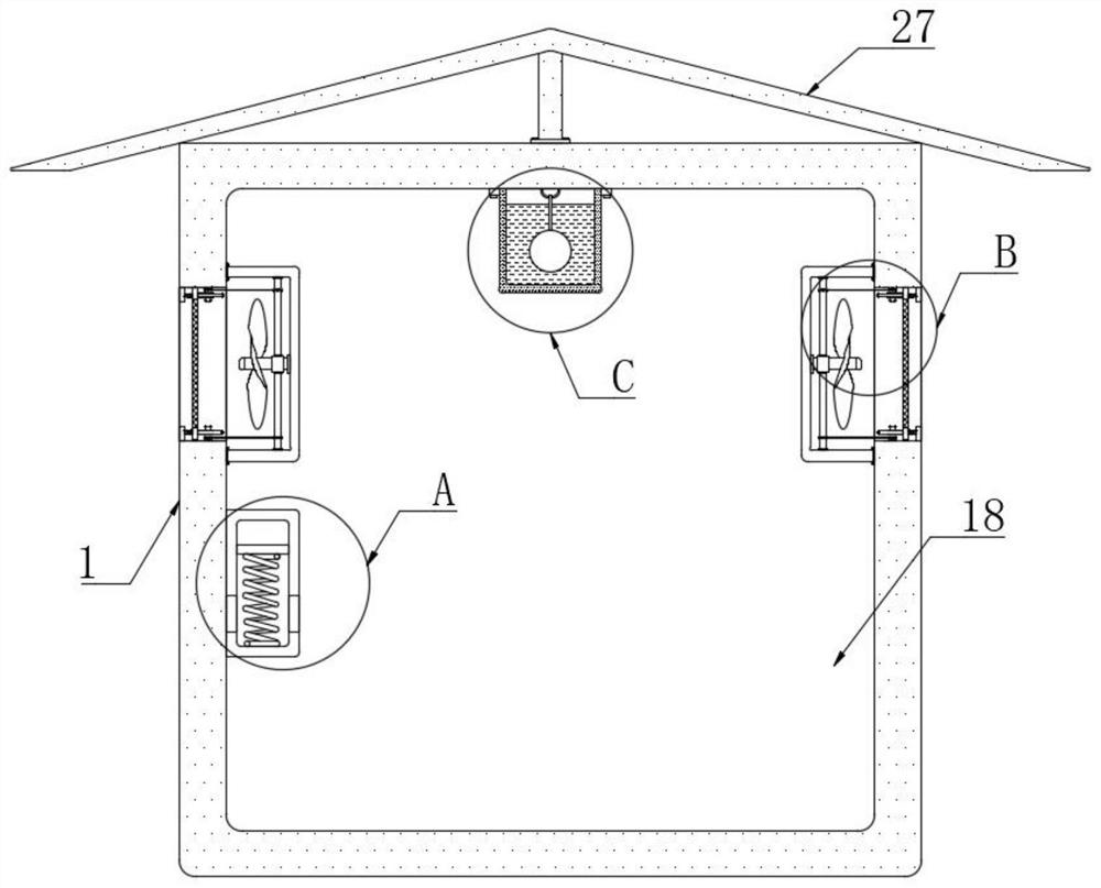
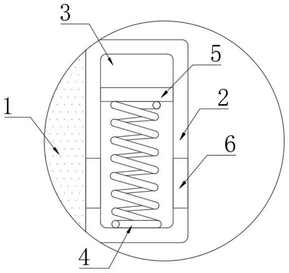
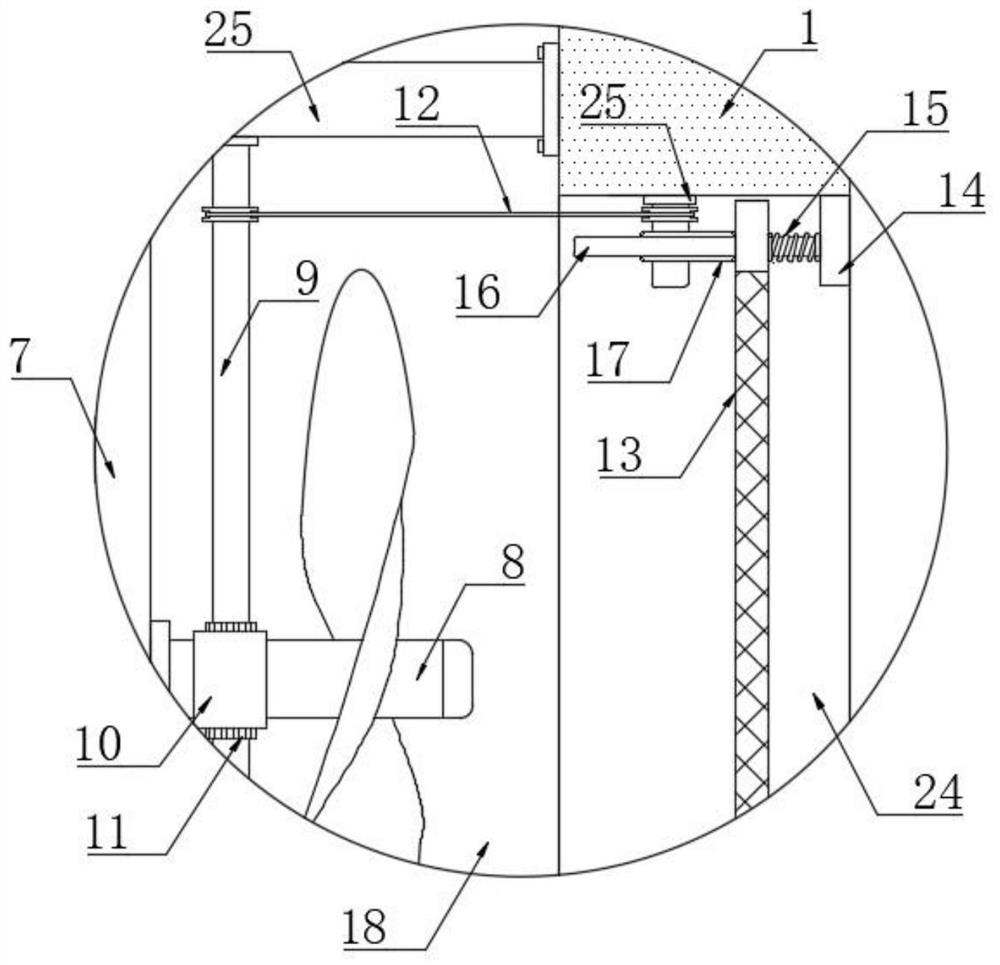
[0025] refer to Figure 1-5 , a transformer automatic heat dissipation protection device, comprising a housing 1, a first installation chamber 18 is provided in the housing 1, openings 24 are provided on the left and right sides of the housing 1, and two vertical openings are arranged on the first installation chamber 18. Two installation rods 7, two installation rods 7 are fixedly connected with the corresponding first installation cavity 18 inner wall by two connecting rods 25, the opposite ends of two installation rods 7 are all equipped with electric cooling fan 8, each installation rod 7 The width is less than half the width of the corresponding opening 24 to en...


PUM


Abstract

The invention discloses an automatic heat dissipation protection device for a transformer, and the device comprises a shell; a first mounting cavity is formed in the shell, openings are formed in the left side and the right side of the shell, two mounting rods are vertically arranged in the first mounting cavity, and the two mounting rods are fixedly connected with the corresponding inner walls of the first mounting cavity through two connecting rods; electric cooling fans are mounted at the opposite ends of the two mounting rods, a first mounting box is mounted on the inner wall of the left side of the first mounting cavity, and a mounting groove is formed in the front side of the first mounting box. According to the device, after the temperature in the shell rises to a certain degree, active heat dissipation can be conducted, it is guaranteed that the transformer is not damaged due to overheating, meanwhile, when an electric cooling fan conducts heat dissipation, a filter screen plate can be driven to shake, it is avoided that dust and sundries block filter screen holes, and heat dissipation is affected, and by arranging structures such as buffer balls, the shaking degree of the shell in strong wind weather can be reduced, so that the transformer is protected.

Description

technical field [0001] The invention relates to the technical field of transformers, in particular to an automatic heat dissipation protection device for a transformer. Background technique [0002] Transformer refers to a device that uses the principle of electromagnetic induction to change AC voltage. Its main components are primary coil, secondary coil and iron core; the main functions of transformer are: voltage conversion, current conversion, impedance conversion, isolation, voltage stabilization, etc. According to the purpose, it can be divided into: power transformers and special transformers; [0003] Existing transformers usually only simply dissipate heat through the cooling vents. Usually, the transformer will not be damaged due to overheating, but sometimes the transformer will be overloaded, and the heat generated at this time will be more. Only through the cooling vents can not be dissipated in time. Overload will lead to overheating and damage to the transfor...

Claims


Application Information

Patent Timeline
Patent Type & Authority Applications(China)
IPC IPC(8): H01F27/02H01F27/08H01F27/28H01F27/40B01D46/76B01D46/10F16F15/02F16F15/023F16F15/28
CPCH01F27/085H01F27/28H01F27/402H01F27/025H01F27/022B01D46/10F16F15/02F16F15/023F16F15/28H01F2027/406F16F2222/08F16F2222/12
Inventor 杨齐全
Owner 杨齐全
Why Eureka
Try Eureka