Search camera capable of adjusting lens in multiple angles based on visual characteristics of birds
A multi-angle, camera technology, applied in the field of search cameras, can solve problems affecting the normal life of birds and inconvenient use
- Summary
- Abstract
- Description
- Claims
- Application Information
AI Technical Summary
Problems solved by technology
Method used
Image
Examples
Embodiment 1
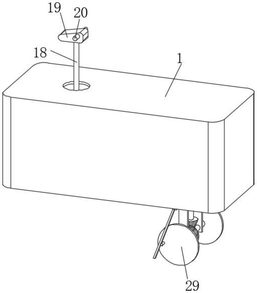
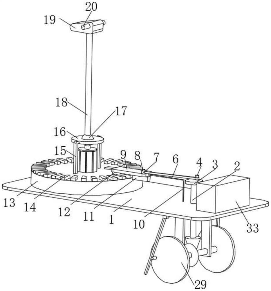
[0032] The present invention provides a technical solution: a search camera with a multi-angle lens adjustment based on the visual characteristics of birds, including a housing 1 and two cameras 20 signal-connected to the recording equipment inside the housing 1, through the setting of the housing 1, the device The internal structure is stored and protected. Through the cooperation of the camera 20 and the recording device inside the shell 1, it is displayed that the external picture is captured in real time by the camera 20, and the video data is stored in the recording device. The recording device in this solution is a disk and related software and hardware conventionally coordinated with the disk. It is an existing device and equipment, so it will not be described too much.
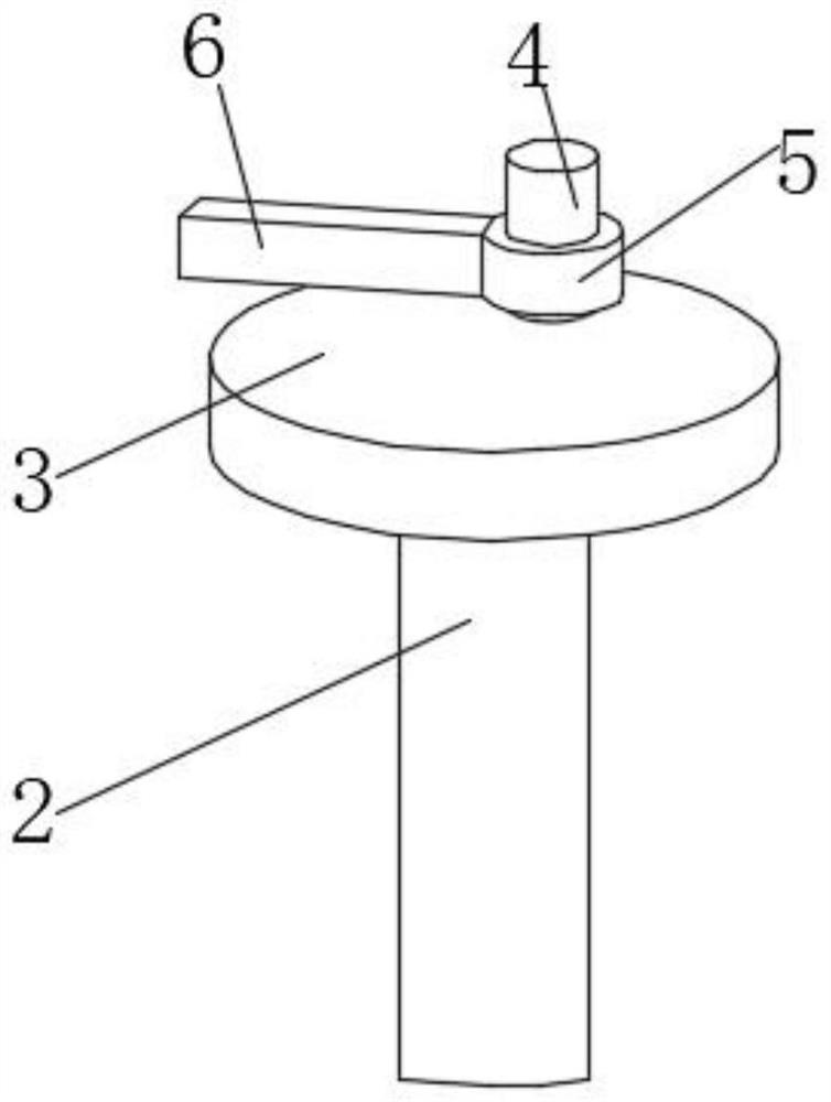
[0033] The lower surface of the shell 1 is provided with a through hole, and through the through hole, a shaft 2 driven by the power mechanism is connected to the rotation limit, and the top of the sha...
Embodiment 2
[0045] It is basically the same as Embodiment 1, furthermore, the slide plate 9 is provided with an adjustment device for rotating and driving the universal ball 17, and the adjustment device includes a connecting column 21, and the top of the connecting column 21 is fixed to the bottom of the universal ball 17. Connection, the bottom of the connecting column 21 is fixedly connected with the connecting plate 22, and the lower surface of the connecting plate 22 is evenly distributed with nine magnetic strips 23, and the magnetic poles on the opposite sides of the nine magnetic strips 23 are the same, and the slide plate 9 is far away from the limit folding bar. One end of 10 is fixedly connected with two magnetic strips 24, and the magnetic poles on one side of the magnetic strip two 24 away from the slide plate 9 are opposite to the magnetic poles on the opposite sides of the nine magnetic strips one 23;
[0046] refer to figure 2 , image 3 with Figure 4 .
[0047] The r...
Embodiment 3
[0049] It is basically the same as Embodiment 2, and what is further is: the shaft one 2 is provided with a moving device that drives the overall movement of the casing 1, and the moving device includes two vertical plates 25 fixedly connected to the lower surface of the casing 1, and the surfaces of the two vertical plates 25 Both are provided with a through hole and are connected with the shaft three 26 through the fixed shaft rotation through the through hole, the arc profile of the shaft three 26 is covered with a bevel gear 1 27, and the surface near the bottom of the shaft one 2 is fixedly sleeved with the bevel gear The two ends of the bevel gear 28 and the two ends of the shaft three 26 are fixedly connected with the moving wheel 29 on the first 27 upper tooth transmission engagement.
[0050] refer to figure 1 , figure 2 with Figure 5 .
[0051] Drive the continuous rotation of the bevel gear two 28 by the shaft one 2, and the bevel gear one 27 that is meshed wit...
PUM
 Abstract
Description
Claims
Application Information
 - R&D
- Intellectual Property
- Life Sciences
- Materials
- Tech Scout
- Unparalleled Data Quality
- Higher Quality Content
- 60% Fewer Hallucinations
Browse by: Latest US Patents, China's latest patents, Technical Efficacy Thesaurus, Application Domain, Technology Topic, Popular Technical Reports.
© 2025 PatSnap. All rights reserved.Legal|Privacy policy|Modern Slavery Act Transparency Statement|Sitemap|About US| Contact US: help@patsnap.com


