Coolant valve for a motor vehicle

A technology for coolant valves and motor vehicles, applied in the direction of engine cooling, coolant flow control, devices for pressure relief on sealing surfaces, etc., can solve the problem of unreliable reduction of impurity deposition, endangering pressure equalization function and The correct function of the regulating body, the failure of the pressure equalization hole can not be prevented, etc.

Pending Publication Date: 2022-02-11
PIERBURG GMBH & CO KG NEUSS
View PDF2 Cites 0 Cited by
  • Summary
  • Abstract
  • Description
  • Claims
  • Application Information

AI Technical Summary

Problems solved by technology

However, axial slots arranged in this way do not prevent failure of the pressure equalization holes
[0005] In the known designs, there is a corresponding disadvantage that the settling of impurities in the through-holes or in the space behind the regulating body cannot be reliably reduced
This jeopardizes the pressure equalization function and correct functioning of the regulatory body

Method used


Image

  • Coolant valve for a motor vehicle
  • Coolant valve for a motor vehicle

Examples


Embodiment Construction

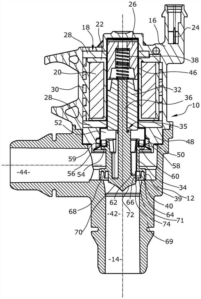
[0024] figure 1 The shown coolant valve consists of a housing 10 which is designed in two parts and has a flow housing 12 in which a flow channel 14 is formed and an actuator housing 16 fixed to the flow housing 12, in which An electromagnetic actuator 18 is arranged in the actuator housing 16 .

[0025] The electromagnetic actuator 18 has an electromagnetic circuit consisting of a coil 20 which is wound on a coil carrier 22 and which can be energized via a plug 24 , as well as a magnetizable core 26 , a return element 28 , a yoke 30 and a movable armature 32 . When the coil 20 is energized, the armature 32 is moved in the direction of the core 26 in a known manner by the magnetic force generated.

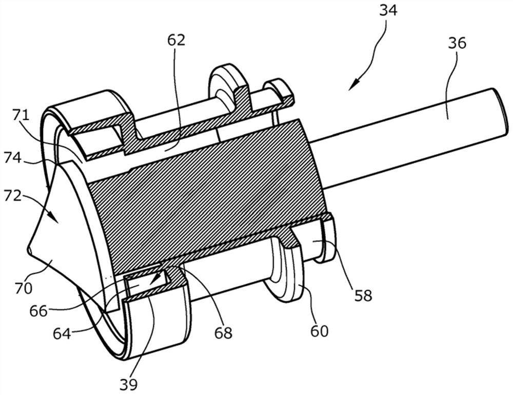
[0026] The armature 32 and the adjusting body 34 form a movement unit 35 by coupling the armature 32 to the adjusting body 34 via a coupling member 36 which is integrally formed with the adjusting body 34 and extends into a bore of the armature 32 and is fixed in In the hole on t...


PUM


Abstract

Motor vehicles coolant valves are known that comprise a housing (10), which has an axial inlet (42) and a radial outlet (44), a flow cross-section which is formed between the inlet (42) and the outlet (44) and is surrounded by a valve seat (40), a control body (34) which can be placed on the valve seat (40) and which can be lifted from the valve seat (40) by means of an actuator (18), and through-bores (62) in the control body (34), via which the inlet (42) is constantly connected to a chamber (52) on the control body (34) side facing away from the inlet (42). The aim of the invention is to maintain the functionality of the coolant valve for as long of a duration as possible even when dirt is present in the coolant. According to the invention, this is achieved in that the control body (34) has a first annular protrusion (39) which extends axially in the direction of the valve seat (40) and by means of which the control body (34) can be placed on the valve seat (40), and an axial groove (68) which extends in the circumferential direction is formed on the control body (34), said axial groove being delimited outwardly by the first annular protrusion (39) and radially inwards by a wall (64) positioned radially between the first annular protrusion (39) and the through-bores (62).

Description

technical field [0001] The invention relates to a coolant valve for a motor vehicle having a housing with an axial inlet and a radial outlet, a flow cross-section formed between the inlet and the outlet and surrounded by a valve seat , a regulating body which can be placed on the valve seat by means of an actuator and which can be lifted from the valve seat, and a through-hole in the regulating body, through which the inlet is always connected to the side of the regulating body facing away from the inlet space. Background technique [0002] Pressure equalization valves are known, in particular for applications in the field of gas delivery, in which pressure equalization in particular can significantly reduce switching times. Mention is made here, for example, of directional valves for turbochargers in motor vehicles. Such a directional control valve is described, for example, in DE 10 2012 010 140 A1. Here, in the closed state of the valve, the passage opening in the adju...

Claims


Application Information

Patent Timeline
Patent Type & Authority Applications(China)
IPC IPC(8): F16K1/36F01P7/14F16K31/06F16K39/02
CPCF01P7/14F16K1/36F16K31/0655F16K31/0693F16K39/022F01P2007/146
Inventor 拜萨特·萨蒂库多米尼克·聂伯格
Owner PIERBURG GMBH & CO KG NEUSS
Why Eureka
Try Eureka