One-time pouring system for U-shaped bottom plate of cable trench and construction method of one-time pouring system

A cable trench and U-shaped technology, which is applied to the one-time pouring system of the cable trench U-shaped bottom plate and its construction field, can solve problems such as impermeability, construction methods that cannot meet construction requirements, and difficulties, so as to improve stability and save production costs , Improve the effect of construction quality

Pending Publication Date: 2022-02-15
WUHAN YIYE CONSTR ENG +1
View PDF8 Cites 0 Cited by
  • Summary
  • Abstract
  • Description
  • Claims
  • Application Information

AI Technical Summary

Problems solved by technology

[0002] In traditional municipal construction, a large number of power supply systems use underground power supply. In conventional cable trench construction, the safety and impermeability of the structure must be ensured. At the same time, the convenience of construction must also be considered. Therefore, distributed pouring is adopted, and pouring first The U-shaped bottom plate of the cable trench, and then pour the side wall and the top plate; when pouring the U-shaped bottom plate of the cable trench, the bottom plate and the side wall must be poured at 30 cm at one time, so as to ensure the safety of the structure on the weak side and ensure the structure It is impermeable, but because there is a certain height difference between the side wall of the U-shaped bottom slab and the bottom slab, it is very difficult to pour the U-shaped bottom slab at one time, and the normal construction method cannot meet the construction requirements

Method used


Image

  • One-time pouring system for U-shaped bottom plate of cable trench and construction method of one-time pouring system
  • One-time pouring system for U-shaped bottom plate of cable trench and construction method of one-time pouring system
  • One-time pouring system for U-shaped bottom plate of cable trench and construction method of one-time pouring system

Examples


Embodiment Construction

[0017] The present invention will be further described below in conjunction with the accompanying drawings and embodiments.

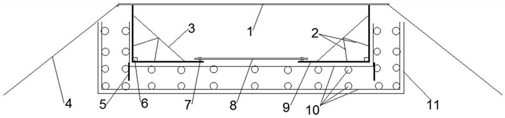
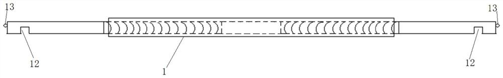
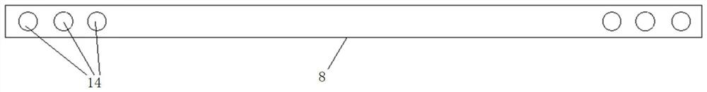
[0018] Such as Figure 1 to Figure 3 As shown, a cable trench U-shaped bottom plate one-time pouring system includes a U-shaped outer mold 11, a U-shaped steel mesh 10 laid in the U-shaped outer mold 11, and a bottom plate installed on the U-shaped steel mesh 10 at the junction of the side walls on both sides. The vertical wire mesh 5 at the place, the right-angled inner mold 9 that is matched at the yin corners on both sides of the U-shaped steel mesh 10, the U-shaped outer mold 11, the U-shaped steel mesh 10, the vertical steel wire mesh 5 and the right-angled inner mold 9 are all along the longitudinal direction. The length is set, there is an interval between the bottom edges of the inner mold 9 at right angles on both sides and is connected by the lower rod 8 along the line, and the top edge is connected by the upper rod 1 along the line, and the t...


PUM


Abstract

The invention discloses a cable trench U-shaped bottom plate one-time pouring system and a construction method thereof. The system comprises a U-shaped outer mold, a U-shaped reinforcing mesh laid in the U-shaped outer mold, vertical steel wire meshes installed at the junctions of an upper bottom plate and side walls on the two sides of the U-shaped reinforcing mesh, and right-angle inner molds matched at internal corners on the two sides of the U-shaped reinforcing mesh; bottom edges of the right-angle inner molds on the two sides are spaced and connected through a lower rod along the line, top edges of the right-angle inner molds on the two sides are connected through an upper rod along the line, two ends of the lower rod are connected with bottom edges of the right-angle inner molds on the two sides through bolts respectively, and a plurality of bolt holes used for adjusting connection positions are distributed in an end of the lower rod along the line; the upper rod is a telescopic rod, and two ends of the upper rod are downwards clamped on top edges of the right-angle inner molds on the two sides through clamping grooves correspondingly and are downwards pulled and fixed through pull ropes correspondingly to achieve the anti-floating effect. The system is advantaged in that the one-time pouring quality of the U-shaped bottom plate is ensured, harmful flowing of concrete is avoided, and the U-shaped bottom plate pouring device can adapt to U-shaped bottom plates of different sizes.

Description

technical field [0001] The invention belongs to the field of municipal engineering, and in particular relates to a one-time pouring system for a U-shaped bottom plate of a cable trench and a construction method thereof. Background technique [0002] In traditional municipal construction, a large number of power supply systems use underground power supply. In conventional cable trench construction, the safety and impermeability of the structure must be ensured. At the same time, the convenience of construction must also be considered. Therefore, distributed pouring is adopted, and pouring first The U-shaped bottom plate of the cable trench, and then pour the side wall and the top plate; when pouring the U-shaped bottom plate of the cable trench, the bottom plate and the side wall must be poured at 30 cm at one time, so as to ensure the safety of the structure on the weak side and ensure the structure However, due to the certain height difference between the side walls of the ...

Claims


Application Information

Patent Timeline
Patent Type & Authority Applications(China)
IPC IPC(8): E02D29/045H02G9/02
CPCE02D29/10E02D29/045H02G9/02E02D2250/0007E02D2250/0023
Inventor 李国华段雪龙
Owner WUHAN YIYE CONSTR ENG
Why Eureka
Try Eureka